DESCRIPTION The radio and display receiver assembly receives a reverse signal from the BKUP LP relay. WIRING DIAGRAM 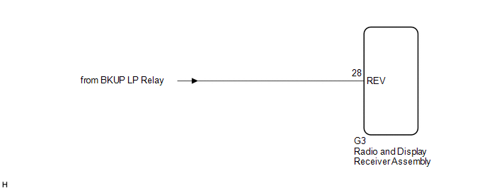 PROCEDURE
(a) Move the shift lever to R and check if the back-up lights come on. OK: The back-up lights come on.
(a) Disconnect the G3 radio and display receiver assembly connector. (b) Measure the voltage according to the value(s) in the table below. Standard Voltage:
|
Toyota Avalon (XX50) 2019-2022 Service & Repair Manual > Electric Parking Brake System(for Hv Model): Freeze Frame Data
FREEZE FRAME DATA FREEZE FRAME DATA HINT: When a DTC is stored, the freeze frame data stores the current vehicle (sensor) state as. The freeze frame data cannot be cleared or updated until the recorded DTCs are cleared. (a) Using the Techstream, the state of the vehicle (sensors) when the system is ...


