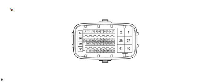
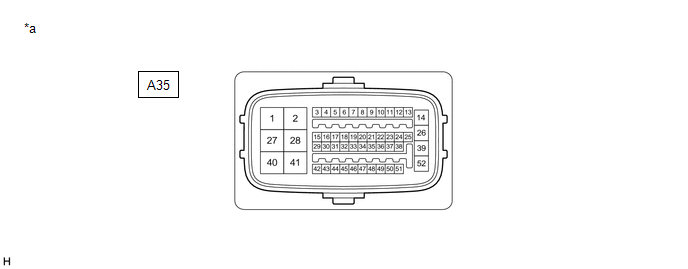
Toyota Avalon (XX50) 2019-2022 Service & Repair Manual: Terminals Of Ecu

TERMINALS OF ECU

TERMINALS OF ECU

*a

Component without harness connected

(Skid Control ECU (Brake Booster with Master Cylinder Assembly))

-

-

Terminal No. (Symbol)

Terminal Description

1 (MRO1)

Motor power supply output 1

2 (MRI1)

Motor power supply input 1

3 (FR+)

Front speed sensor RH (+) power supply output

4 (FR-)

Front speed sensor RH (-) signal input

5 (+BI2)

+BI2 power source input

6

- (Not used)

7 (RR+)

Rear speed sensor RH (+) power supply output

8 (RR-)

Rear speed sensor RH (-) signal input

9 (IG2)

IG2 power source input

10

- (Not used)

11 (SP1)

Speed sensor signal output

12 (STP)

Stop light switch assembly input

13 (SKG1)

Brake pedal stroke sensor assembly ground 1

14 (+BS)

ABS solenoid drive power output

15 (+BI1)

+BI1 power source input

16 (LBL)

Brake fluid level warning switch (Brake booster with master cylinder assembly) input

17 (SKS1)

Brake pedal stroke sensor assembly signal input 1

18 (CSW)

VSC OFF switch input

19 (SKS2)

Brake pedal stroke sensor assembly signal input 2

20 (CSW2)

Brake hold switch (Electric parking brake switch assembly) input

21 (VSK2)

Brake pedal stroke sensor assembly power supply output 2

22 (STPO)

Stop light control relay (Stop light switch assembly) output

23 (IG1)

IG1 power source input

24 (CTY)

Front door courtesy light switch assembly LH input

25 (VSK1)

Brake pedal stroke sensor assembly power supply output 1

26 (GND1)

Skid control ECU (Brake booster with master cylinder assembly) ground 1

27 (MRO2)

Motor power supply output 2

28 (MRI2)

Motor power supply input 2

29 (CA2L)

CAN communication line 2 (L)

30 (CA2H)

CAN communication line 2 (H)

31 (FL+)

Front speed sensor LH (+) power supply output

32 (FL-)

Front speed sensor LH (-) signal input

33 (SKG2)

Brake pedal stroke sensor assembly ground 2

34 (RL+)

Rear speed sensor LH (+) power supply output

35 (RL-)

Rear speed sensor LH (-) signal input

36

- (Not used)

37 (STP2)

Stop light control relay (Stop light switch assembly) input

38

- (Not used)

39 (GND2)

Skid control ECU (Brake booster with master cylinder assembly) ground 2

40 (+BM)

ABS motor drive power output

41 (BM)

ABS motor relay power supply input

42 (CA1L)

CAN communication line 1 (L)

43 (CA1H)

CAN communication line 1 (H)

44 (SFRR)

Front ABS reduction solenoid RH (-) output

45 (SFLR)

Front ABS reduction solenoid LH (-) output

46 (SRRR)

Rear ABS reduction solenoid RH (-) output

47 (SRLR)

Rear ABS reduction solenoid LH (-) output

48 (SFRH)

Front ABS holding solenoid RH (-) output

49 (SFLH)

Front ABS holding solenoid LH (-) output

50 (SRRH)

Rear ABS holding solenoid RH (-) output

51 (SRLH)

Rear ABS holding solenoid LH (-) output

52 (BS)

ABS solenoid relay power supply input

TERMINAL INSPECTION

(a) Disconnect the connector and measure the voltage or resistance on the wire harness side.

*a

Front view of wire harness connector

(to Skid Control ECU (Brake Booster with Master Cylinder Assembly))

-

-

HINT:

The voltage cannot be measured with the connector connected to the skid control ECU (brake booster with master cylinder assembly) as the connector is watertight.

Standard

Terminal No. (Symbol)

Wiring Color

Terminal Description

Condition

Specified Condition

A35-2 (MRI1) - Body ground

B - Body ground

Motor power supply input 1

Always

11 to 14 V

A35-5 (+BI2) - Body ground

BE - Body ground

+BI2 power source input

Always

11 to 14 V

A35-9 (IG2) - Body ground

LA-R - Body ground

IG2 power source input

Power switch on (IG)

11 to 14 V

A35-12 (STP) - Body ground

SB - Body ground

Stop light switch assembly input

Stop light switch assembly on → off

(Brake pedal depressed → released)

11 to 14 V → 1.5 V or less

A35-15 (+BI1) - Body ground

SB - Body ground

+BI1 power source input

Always

11 to 14 V

A35-16 (LBL) - Body ground

R - Body ground

Brake fluid level warning switch (Brake booster with master cylinder assembly) input

Brake fluid level warning switch off → on

1.84 to 2.16 kΩ → Below 1 Ω

A35-18 (CSW) - Body ground

P - Body ground

VSC OFF switch input

VSC OFF switch held on → off (Released)

Below 1 Ω → 10 kΩ or higher

A35-20 (CSW2) - Body ground

LG - Body ground

Brake hold switch (Electric parking brake switch assembly) input

Brake hold switch (Electric parking brake switch assembly) held on → off (Released)

Below 1 Ω → 10 kΩ or higher

A35-22 (STPO) - Body ground

L - Body ground

Stop light control relay (Stop light switch assembly) output

Always

11 to 14 V

A35-23 (IG1) - Body ground

LA-P - Body ground

IG1 power source input

Power switch on (IG)

11 to 14 V

A35-24 (CTY) - Body ground

V - Body ground

Front door courtesy light switch assembly LH input

Driver door closed → open

11 to 14 V → 1.5 V or less

A35-26 (GND1) - Body ground

LA - Body ground

Skid control ECU (Brake booster with master cylinder assembly) ground 1

Always

Below 1 Ω

A35-28 (MRI2) - Body ground

G - Body ground

Motor power supply input 2

Always

11 to 14 V

A35-37 (STP2) - Body ground

BE - Body ground

Stop light control relay (Stop light switch assembly) input

Stop light switch assembly on → off

(Brake pedal depressed → released)

11 to 14 V → 1.5 V or less

A35-39 (GND2) - Body ground

W-B - Body ground

Skid control ECU (Brake booster with master cylinder assembly) ground 2

Always

Below 1 Ω

A35-41 (BM) - Body ground

L - Body ground

ABS motor relay power supply input

Always

11 to 14 V

A35-52 (BS) - Body ground

LG - Body ground

ABS solenoid relay power supply input

Always

11 to 14 V

    System Diagram

    Test Mode Procedure

    See More:

    Toyota Avalon (XX50) 2019-2022 Service & Repair Manual > Dynamic Radar Cruise Control System(for Hv Model): Operation Check
    OPERATION CHECK INPUT SIGNAL CHECK (a) Connect the Techstream to the DLC3. (b) Check the steering pad switch assembly using the Data List function of the Techstream (cruise control main switch, -SET switch, +RES switch and CANCEL switch). Click here *1 Steering Pad Switch Assembly *a Cruise Control ...

    Toyota Avalon (XX50) 2019-2022 Owners Manual

    Toyota Avalon (XX50) 2019-2022 Service & Repair Manual

    © 2024 Copyright www.tavalon.net
    0.0218