Components COMPONENTS ILLUSTRATION
|
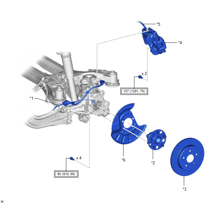
*1 | NO. 2 PARKING BRAKE WIRE ASSEMBLY |
*2 | REAR AXLE HUB AND BEARING ASSEMBLY | |
*3 | REAR DISC |
*4 | REAR DISC BRAKE CALIPER ASSEMBLY | |
*5 | REAR FLEXIBLE HOSE |
*6 | REAR DISC BRAKE DUST COVER SUB-ASSEMBLY |
 |
Tightening torque for "Major areas involving basic vehicle performance such as moving/turning/stopping": N*m (kgf*cm, ft.*lbf) |
- | - | Installation INSTALLATION CAUTION / NOTICE / HINT
HINT:
- Use the same procedure for the RH side and LH side.
- The following procedure is for the LH side.
- If the rear speed sensor rotor needs to be replaced, replace the rear axle hub and bearing assembly.
- The rear speed sensor is a component of the rear axle hub and bearing
assembly. If the rear speed sensor is malfunctioning, replace the rear
axle hub and bearing assembly.
PROCEDURE 1. INSTALL REAR AXLE HUB AND BEARING ASSEMBLY
Click here  Removal REMOVAL CAUTION / NOTICE / HINT
The
necessary procedures (adjustment, calibration, initialization, or
registration) that must be performed after parts are removed, installed,
or replaced during rear speed sensor (rear axle hub and bearing
assembly) removal/installation are shown below. Necessary Procedures After Parts Removed/Installed/Replaced (for HV Model:) |
Replaced Part or Performed Procedure |
Necessary Procedure | Effect/Inoperative Function when Necessary Procedure not Performed |
Link | |
*: When performing learning using the Techstream.
Click here  | |
Auxiliary battery terminal is disconnected/reconnected |
Perform steering sensor zero point calibration |
Lane Departure Alert System (w/ Steering Control) |
| |
Pre-collision System | |
Intelligent Clearance Sonar System* | |
Lighting System (for HV Model with Cornering Light) | |
Memorize steering angle neutral point |
Parking Assist Monitor System |
| |
Panoramic View Monitor System |
| for HV Model:
- When removing or installing the rear disc brake caliper assembly,
pushing back the disc brake piston may cause a large clearance between
the brake pads and brake disc. When the brake pedal is depressed with a
large clearance between the brake pads and the brake disc, DTC C1214
related to abnormal brake fluid pressure may be stored. Make sure to
clear any DTCs after performing this procedure.
- While the auxiliary battery is connected, even if the power switch is
off, the brake control system activates when the brake pedal is
depressed or any door courtesy switch turns on. Therefore, when
servicing the brake system components, do not operate the brake pedal or
open/close the doors while the auxiliary battery is connected.
HINT:
- Use the same procedure for the RH side and LH side.
- The following procedure is for the LH side.
- If the rear speed sensor rotor needs to be replaced, replace the rear axle hub and bearing assembly.
- The rear speed sensor is a component of the rear axle hub and bearing
assembly. If the rear speed sensor is malfunctioning, replace the rear
axle hub and bearing assembly.
PROCEDURE 1. REMOVE REAR AXLE HUB AND BEARING ASSEMBLY
Click here |


