REMOVAL CAUTION / NOTICE / HINT The necessary procedures (adjustment, calibration, initialization, or registration) that must be performed after parts are removed, installed, or replaced during brake pedal support assembly removal/installation are shown below. Necessary Procedures After Parts Removed/Installed/Replaced
NOTICE: While the auxiliary battery is connected, even if the power switch is off, the brake control system activates when the brake pedal is depressed or any door courtesy switch turns on. Therefore, when servicing the brake system components, do not operate the brake pedal or open/close the doors while the auxiliary battery is connected. PROCEDURE 1. REMOVE BRAKE BOOSTER WITH MASTER CYLINDER ASSEMBLY Click here
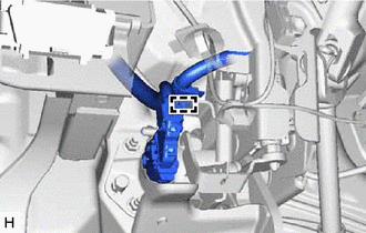
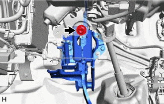
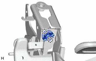
2. REMOVE BRAKE PEDAL STROKE SENSOR ASSEMBLY Click here 3. REMOVE STOP LIGHT SWITCH ASSEMBLY Click here 4. REMOVE BRAKE PEDAL SUPPORT ASSEMBLY
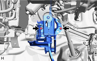
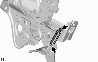
(d) Remove the brake pedal support assembly while avoiding the stud bolts of the brake booster support base. NOTICE: Be careful not to deform the bracket of the instrument panel reinforcement assembly. 5. REMOVE BRAKE PEDAL RETURN SPRING
6. REMOVE STOP LIGHT SWITCH MOUNTING ADJUSTER
7. REMOVE BRAKE PEDAL PAD (a) Remove the brake pedal pad from the brake pedal support assembly. | |||||||||||||||||||||||||||||||||||||||
Toyota Avalon (XX50) 2019-2022 Service & Repair Manual > Pre-collision System(for Hv Model): Lost Communication with Yaw Rate Sensor Module (U0125,U0126,U0129,U0155,U0293)
DESCRIPTION The driving support ECU assembly uses the millimeter wave radar sensor assembly to detect objects in front of the vehicle. Based on signals from the millimeter wave radar sensor assembly, the driving support ECU assembly sends pre-collision system control operation signals. These DTCs ar ...