|
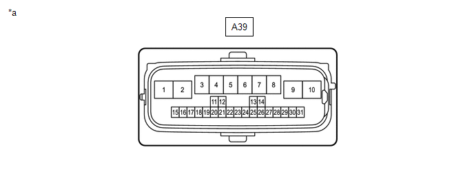
Terminal No. (Symbol) | Wiring Color |
Terminal Description | Condition |
Specified Condition |
|
A39-9 (BEPB) - Body ground |
R - Body ground | Parking brake power supply |
Power switch off | 11 to 14 V |
|
A39-26 (IG) - Body ground |
B - Body ground | IG power supply |
Power switch on (IG) |
8 to 16 V |
|
A39-2 (EGND) - Body ground |
W-B - Body ground | Ground |
Always | Below 1 Ω |
|
A39-13 (POL) - Body ground |
L - Body ground | Electric parking brake switch indicator light |
- | - |
|
A39-14 (SWI1) - Body ground |
P - Body ground | Electric parking brake switch (electric parking brake switch assembly) |
- | - |
|
A39-24 (SWI2) - Body ground |
W - Body ground | Electric parking brake switch (electric parking brake switch assembly) |
- | - |
|
A39-20 (SWO1) - Body ground |
SB - Body ground | Electric parking brake switch (electric parking brake switch assembly) |
- | - |
|
A39-22 (SWO2) - Body ground |
V - Body ground | Electric parking brake switch (electric parking brake switch assembly) |
- | - |
|
A39-4 (MRR+) - Body ground |
LA-Y - Body ground | Parking brake motor RH (parking brake actuator assembly RH) (+) |
- | - |
|
A39-3 (MRR-) - Body ground |
LA-L - Body ground | Parking brake motor RH (parking brake actuator assembly RH) (-) |
- | - |
|
A39-7 (MRL+) - Body ground |
LA-G - Body ground | Parking brake motor LH (parking brake actuator assembly LH) (+) |
- | - |
|
A39-8 (MRL-) - Body ground |
LA-W - Body ground | Parking brake motor LH (parking brake actuator assembly LH) (-) |
- | - |
|
A39-27 (SPD) - Body ground |
L - Body ground | Vehicle speed direct input |
- | - |
|
A39-12 (CANH) - Body ground |
B - Body ground | CAN communication line H |
- | - |
|
A39-11 (CANL) - Body ground |
W - Body ground | CAN communication line L |
- | - |