ON-VEHICLE INSPECTION CAUTION / NOTICE / HINT The necessary procedures (adjustment, calibration, initialization, or registration) that must be performed after parts are removed and installed, or replaced during front axle hub sub-assembly on-vehicle inspection are shown below. Necessary Procedures After Parts Removed/Installed/Replaced (for HV Model:)
HINT:
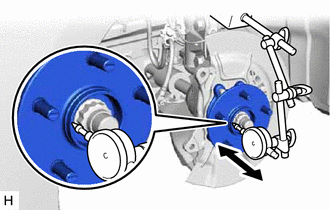
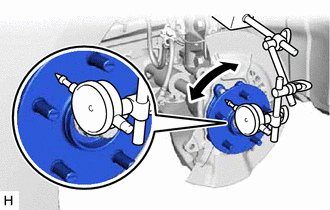
PROCEDURE 1. PRECAUTION (for HV Model) NOTICE: After turning the power switch off, waiting time may be required before disconnecting the cable from the negative (-) auxiliary battery terminal. Therefore, make sure to read the disconnecting the cable from the negative (-) auxiliary battery terminal notices before proceeding with work. Click here 2. DISABLE BRAKE CONTROL (for HV Model) Click here 3. REMOVE FRONT WHEEL Click here 4. SEPARATE FRONT FLEXIBLE HOSE Click here 5. SEPARATE FRONT DISC BRAKE CALIPER ASSEMBLY Click here 6. REMOVE FRONT DISC Click here 7. INSPECT FRONT AXLE HUB BEARING LOOSENESS
8. INSPECT FRONT AXLE HUB RUNOUT
9. INSTALL FRONT DISC Click here 10. INSTALL FRONT DISC BRAKE CALIPER ASSEMBLY Click here
11. INSTALL FRONT FLEXIBLE HOSE Click here
12. INSTALL FRONT WHEEL Click here
13. CONNECT CABLE TO NEGATIVE AUXILIARY BATTERY TERMINAL (for HV Model) (a) Connect the reservoir level switch connector. (b) Connect the cable to the negative (-) auxiliary battery terminal. Click here (c) Turn the power switch on (READY). (d) Depress the brake pedal and release it. (e) Clear the DTCs. Click here | ||||||||||||||||||||||||||
Toyota Avalon (XX50) 2019-2022 Service & Repair Manual > Hybrid Control System: Throttle/Pedal Position Sensor/Switch "D" Circuit Short to Auxiliary Battery (P212012,...,P21382B)
DTC SUMMARY MALFUNCTION DESCRIPTION The hybrid vehicle control ECU calculates the accelerator pedal opening angle based on the output voltage of the main sensor (VPA) and sub sensor (VPA2) of the accelerator pedal sensor assembly. If the output voltage of either the main sensor (VPA) or sub sensor ( ...