Toyota Avalon Service & Repair Manual: Reassembly

REASSEMBLY

CAUTION / NOTICE / HINT

HINT:

  • Use the same procedure for the RH side and LH side.
  • The following procedure is for the LH side.

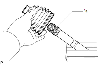
PROCEDURE

1. INSTALL FRONT AXLE OUTBOARD JOINT BOOT

(a) Secure the drive shaft in a vise between aluminum plates.

NOTICE:

Do not overtighten the vise.

(b) Wrap the splines of the front drive outboard joint shaft assembly with protective tape to prevent the boot from being damaged.

*a

Protective Tape

(c) Install new parts to the front drive outboard joint shaft assembly in the following order:

*1

Front Drive Outboard Joint Shaft Assembly

*2

Front No. 2 Axle Outboard Joint Boot Clamp

*3

Front Axle Outboard Joint Boot

*4

Front Axle Outboard Joint Boot Clamp

Outboard Joint Side

Inboard Joint Side

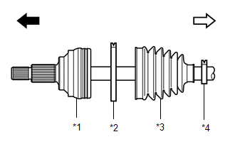
(1) Front No. 2 axle outboard joint boot clamp

(2) Front axle outboard joint boot

(3) Front axle outboard joint boot clamp

(d) Pack the joint portion of the front drive outboard joint shaft assembly and front axle outboard joint boot with grease.

Standard Grease Capacity (for Gasoline Model):

86 g (3.03 oz)

Standard Grease Capacity (for HV Model):

110 g (3.88 oz)

(e) Install the front axle outboard joint boot to the front drive outboard joint shaft assembly groove.

NOTICE:

  • Do not allow grease to adhere to the boot clamp track of the outboard joint boot.
  • Keep the inside of the outboard joint boot free of foreign matter.

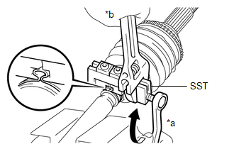
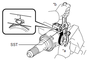
2. INSTALL FRONT AXLE OUTBOARD JOINT BOOT CLAMP

(a) Secure the drive shaft in a vise between aluminum plates.

NOTICE:

Do not overtighten the vise.

(b) Install the front axle outboard joint boot clamp to the front axle outboard joint boot.

(c) Place SST to the front axle outboard joint boot clamp, press it against the boot and slightly tighten SST.

SST: 09521-24010

*a

Turn

*b

Hold

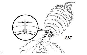
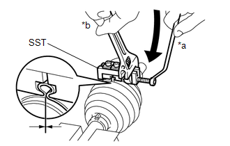
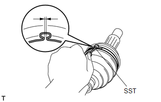
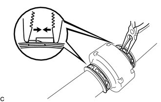
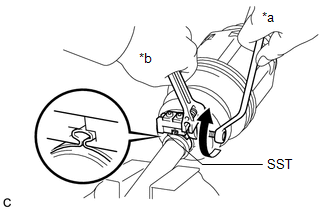
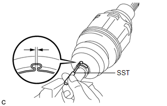
(d) Tighten SST so that the front axle outboard joint boot clamp is pinched.

NOTICE:

Do not overtighten SST.

(e) Remove SST.

(f) Using SST, measure the clearance of the front axle outboard joint boot clamp.

SST: 09240-00021

Clearance:

0.5 to 1.5 mm (0.0197 to 0.0590 in.)

If the clearance is not as specified, retighten SST.

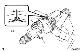
3. INSTALL FRONT NO. 2 AXLE OUTBOARD JOINT BOOT CLAMP

(a) Secure the drive shaft in a vise between aluminum plates.

NOTICE:

Do not overtighten the vise.

(b) Install the front No. 2 axle outboard joint boot clamp to the front axle outboard joint boot.

(c) Place SST onto the front No. 2 axle outboard joint boot clamp, press it against the boot and slightly tighten SST.

SST: 09521-24010

*a

Turn

*b

Hold

(d) Tighten SST so that the front No. 2 axle outboard joint boot clamp is pinched.

NOTICE:

Do not overtighten SST.

(e) Remove SST.

(f) Using SST, measure the clearance of the front No. 2 axle outboard joint boot clamp.

SST: 09240-00021

Clearance:

0.5 to 1.5 mm (0.0197 to 0.0590 in.)

If the clearance is not as specified, retighten SST.

4. INSTALL FRONT DRIVE SHAFT DAMPER

(a) Temporarily install the front drive shaft damper and 2 new front drive shaft damper clamps to the front drive outboard joint shaft assembly as shown in the illustration.

*1

Front Drive Shaft Damper Clamp

*2

Front Drive Shaft Damper

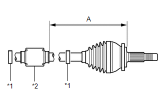
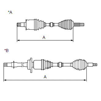
(b) Set the dimension (A) as specified below.

Dimension (A) (for Gasoline Model):

226.9 to 230.9 mm (8.94 to 9.09 in.)

Dimension (A) (for HV Model):

223.4 to 227.4 mm (8.80 to 8.95 in.)

5. INSTALL FRONT DRIVE SHAFT DAMPER CLAMP (for LH Side)

(a) Secure the drive shaft in a vise between aluminum plates.

NOTICE:

Do not overtighten the vise.

(b) Install the 2 front drive shaft damper clamps to the front drive shaft damper.

NOTICE:

Make sure to install the clamps in the correct position.

(c) Place SST onto the front drive shaft damper clamp, press it against the damper and slightly tighten SST.

SST: 09521-24010

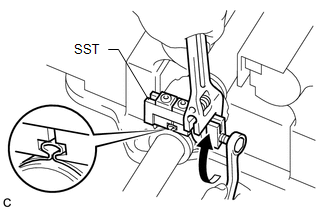
(d) Tighten SST so that the front drive shaft damper clamp is pinched.

NOTICE:

Do not overtighten SST.

(e) Remove SST.

(f) Using SST, measure the clearance of the front drive shaft damper clamp.

SST: 09240-00021

Clearance:

0.5 to 1.5 mm (0.0197 to 0.0590 in.)

If the clearance is not as specified, retighten SST.

6. INSTALL FRONT DRIVE SHAFT DAMPER CLAMP (for RH Side)

(a) Secure the drive shaft in a vise between aluminum plates.

NOTICE:

Do not overtighten the vise.

(b) Using needle-nose pliers, install the 2 front drive shaft damper clamps as shown in the illustration.

NOTICE:

  • Be sure to install the clamps in the correct position.
  • Do not damage the front drive shaft damper.

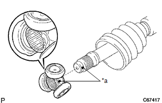
7. INSTALL FRONT DRIVE INBOARD JOINT ASSEMBLY

(a) Install new parts to the front drive outboard joint shaft assembly in the following order:

*1

Front Axle Inboard Joint Boot Clamp

*2

Front Axle Inboard Joint Boot

*3

Front No. 2 Axle Inboard Joint Boot Clamp

*a

Protective Tape

Outboard Joint Side

Inboard Joint Side

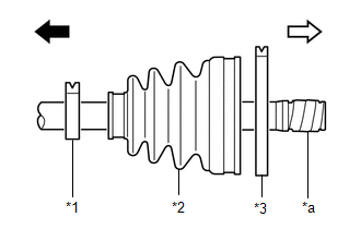
(1) Front axle inboard joint boot clamp

(2) Front axle inboard joint boot

(3) Front No. 2 axle inboard joint boot clamp

(b) Secure the drive shaft in a vise between aluminum plates.

NOTICE:

Do not overtighten the vise.

(c) Remove the protective tape.

(d) Align the matchmarks and install the tripod joint to the front drive outboard joint shaft assembly.

NOTICE:

Face the serrated side of the tripod joint outward and install it to the outboard joint end.

*a

Matchmark

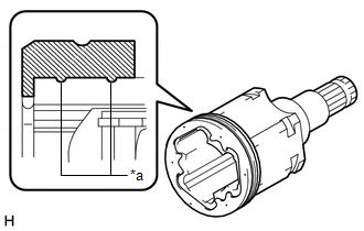
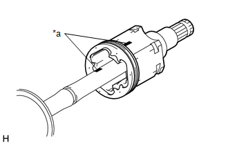
(e) Using a brass bar and a hammer, install the tripod joint to the front drive outboard joint shaft assembly.

NOTICE:

  • Do not tap the rollers.
  • Keep the tripod joint free of foreign matter.
  • Be sure to install the tripod joint in the correct direction.

(f) Using a snap ring expander, install a new shaft snap ring to the front drive outboard joint shaft assembly.

(g) Pack the front drive inboard joint assembly and front axle inboard joint boot with grease.

Standard Grease Capacity:

195 g (6.88 oz)

(h) Install a new front axle inboard joint grommet to the front drive inboard joint assembly.

NOTICE:

  • Securely fit the protrusion on the front axle inboard joint grommet into the front drive inboard joint assembly.
  • Make sure that the lip of the front axle inboard joint grommet is not damaged.

*a

Lip

(i) Align the matchmarks and install the front drive inboard joint assembly to the front drive outboard joint shaft assembly.

*a

Matchmark

8. INSTALL FRONT AXLE INBOARD JOINT BOOT

(a) Install the front axle inboard joint boot to the front drive inboard joint assembly.

(b) Check whether the dimension (A) of each drive shaft is within the specification.

NOTICE:

Keep the drive shaft assembly level during inspection.

Dimension (A) (for Gasoline Model):

for LH Side

598.75 mm (1.96 ft.)

for RH Side

924.55 mm (3.03 ft.)

Dimension (A) (for HV Model):

for LH Side

604.71 mm (1.98 ft.)

for RH Side

905.65 mm (2.97 ft.)

*A

for LH Side

*B

for RH Side

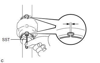
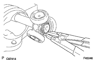
9. INSTALL FRONT AXLE INBOARD JOINT BOOT CLAMP

(a) Secure the drive shaft in a vise between aluminum plates.

NOTICE:

Do not overtighten the vise.

(b) Install the front axle inboard joint boot clamp to the front axle inboard joint boot.

(c) Place SST onto the front axle inboard joint boot clamp, press it against the boot and slightly tighten SST.

SST: 09521-24010

*a

Turn

*b

Hold

(d) Tighten SST so that the front axle inboard joint boot clamp is pinched.

NOTICE:

Do not overtighten SST.

(e) Remove SST.

(f) Using SST, measure the clearance of the front axle inboard joint boot clamp.

SST: 09240-00021

Clearance:

0.5 to 1.5 mm (0.0197 to 0.0590 in.)

If the clearance is not as specified, retighten SST.

10. INSTALL FRONT NO. 2 AXLE INBOARD JOINT BOOT CLAMP

(a) Secure the drive shaft in a vise between aluminum plates.

NOTICE:

Do not overtighten the vise.

(b) Install the front No. 2 axle inboard joint boot clamp to the front axle inboard joint boot.

(c) Place SST onto the front No. 2 axle inboard joint boot clamp, press it against the boot and slightly tighten SST.

SST: 09521-24010

*a

Turn

*b

Hold

(d) Tighten SST so that the front No. 2 axle inboard joint boot clamp is pinched.

NOTICE:

Do not overtighten SST.

(e) Remove SST.

(f) Using SST, measure the clearance of the front No. 2 axle inboard joint boot clamp.

SST: 09240-00021

Clearance:

0.5 to 1.5 mm (0.0197 to 0.0590 in.)

If the clearance is not as specified, retighten SST.

11. INSPECT FRONT DRIVE SHAFT ASSEMBLY

Click here

    Installation

    Removal

    See More:

    Toyota Avalon Owners Manual > Multi-information display: Summary of functions
    The multi-information display presents the driver with a variety of driving- related data, such as the current outside temperature. The multi-information display can also be used to change the display settings and other settings. Indicators Driving assist system status display area Displays the oper ...

    Toyota Avalon Owners Manual

    Toyota Avalon Service & Repair Manual

    © 2024 Copyright www.tavalon.net
    0.0196