INSTALLATION PROCEDURE 1. INSTALL TRANSMISSION CONTROL CABLE ASSEMBLY
(b) Engage the 2 claws to install a new clip to the transmission control cable assembly.
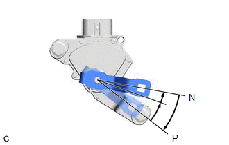
(d) Connect the transmission control cable assembly to the control shaft lever with the nut. Torque: 12 N·m {122 kgf·cm, 9 ft·lbf} NOTICE: Before installing the transmission control cable assembly, check that the shift lever position sensor and the shift lever are in N. (e) Connect the transmission control cable assembly to the inverter with converter assembly with the 3 bolts. Torque: 12 N·m {122 kgf·cm, 9 ft·lbf} (f) Connect the transmission control cable assembly to the vehicle body with the 2 nuts. Torque: 6.0 N·m {61 kgf·cm, 53 in·lbf} (g) Pass the transmission control cable assembly into the vehicle and install the transmission control cable assembly to the vehicle body with the 2 nuts. Torque: 6.0 N·m {61 kgf·cm, 53 in·lbf} 2. CONNECT ENGINE ROOM MAIN WIRE Click here 3. INSTALL NO. 1 CONSOLE BOX DUCT (a) Install the No. 1 console box duct. 4. INSTALL TRANSMISSION FLOOR SHIFT ASSEMBLY Click here 5. INSTALL FRONT LOWER NO. 1 FLOOR HEAT INSULATOR (a) Install the front lower No. 1 floor heat insulator to the vehicle body with the 2 nuts. Torque: 4.9 N·m {50 kgf·cm, 43 in·lbf} 6. INSTALL FRONT EXHAUST PIPE ASSEMBLY Click here 7. INSTALL AIR CLEANER ASSEMBLY WITH AIR CLEANER HOSE Click here 8. INSTALL NO. 1 ENGINE COVER SUB-ASSEMBLY Click here 9. INSTALL INLET AIR CLEANER ASSEMBLY Click here 10. INSTALL COOL AIR INTAKE DUCT SEAL Click here 11. INSPECT SHIFT LEVER POSITION Click here 12. ADJUST SHIFT LEVER POSITION Click here |
Toyota Avalon (XX50) 2019-2022 Service & Repair Manual > Knee Airbag Assembly(for Front Passenger Side): Installation
INSTALLATION PROCEDURE 1. INSTALL LOWER NO. 2 INSTRUMENT PANEL AIRBAG ASSEMBLY (a) Check that the engine switch (for Gasoline Model) or power switch (for HV Model) is off. (b) Check that the cable is disconnected from the negative (-) auxiliary battery terminal. CAUTION: Wait at least 90 seconds aft ...