DESCRIPTION Moving the
shift lever to S enables the shift range to be selected. The shift range
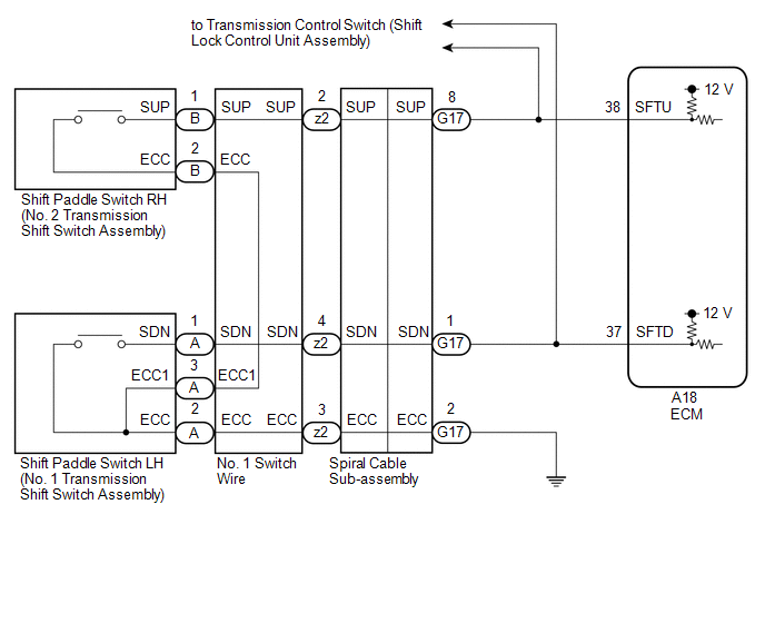
can be selected by operating the "+" or "-" shift paddle switch. WIRING DIAGRAM
 CAUTION / NOTICE / HINT
NOTICE: After
turning the engine switch off, waiting time may be required before
disconnecting the cable from the negative (-) battery terminal.
Therefore, make sure to read the disconnecting the cable from the
negative (-) battery terminal notices before proceeding with work. Click here
 PROCEDURE
| 1. |
READ VALUE USING TECHSTREAM (SPORT SHIFT SWITCH STATUS) |
(a) Connect the Techstream to the DLC3. (b) Turn the engine switch on (IG).
(c) Turn the Techstream on. (d) Enter the following menus: Powertrain / Engine / Data List.
(e) According to the display on the Techstream, read the Data List. Powertrain > Engine > Data List
|
Tester Display | Measurement Item |
Range | Normal Condition |
Diagnostic Note | |
Sport Shift Up SW | Sport shift up switch status |
ON or OFF |
- ON: Shift lever held in "+" or "+" shift paddle switch operated
- OFF: Shift lever not held in "+" and "+" shift paddle switch released
| - | |
Sport Shift Down SW | Sport shift down switch status |
ON or OFF |
- ON: Shift lever held in "-" or "-" shift paddle switch operated
- OFF: Shift lever not held in "-" and "-" shift paddle switch released
| - | Powertrain > Engine > Data List
|
Tester Display | | Sport Shift Up SW | |
Sport Shift Down SW |
|
Result | Proceed to | |
Data List values are normal |
A | | Data List values are not normal |
B |
| A |
 | CHECK FOR INTERMITTENT PROBLEMS |
|
B |
 | |
| 2. |
CHECK HARNESS AND CONNECTOR (SHIFT PADDLE SWITCH CIRCUIT) |
(a) Disconnect the A18 ECM connector. (b) Measure the resistance according to the value(s) in the table below.
Standard Resistance: |
Tester Connection | Condition |
Specified Condition | |
A18-38 (SFTU) - Body ground |
"+" (Up shift) shift paddle switch operated and held |
Below 13 Ω | |
"+" (Up shift) shift paddle switch not operated |
10 kΩ or higher | |
A18-37 (SFTD) - Body ground |
"-" (Down shift) shift paddle switch operated and held |
Below 13 Ω | |
"-" (Down shift) shift paddle switch not operated |
10 kΩ or higher |
| OK |
| PROCEED TO NEXT SUSPECTED AREA SHOWN IN PROBLEM SYMPTOMS TABLE |
|
NG | |
| |
| 3. |
CHECK HARNESS AND CONNECTOR (SPIRAL CABLE SUB-ASSEMBLY - ECM) |
(a) Disconnect the G17 spiral cable sub-assembly connector. (b) Disconnect the A18 ECM connector.
(c) Measure the resistance according to the value(s) in the table below.
Standard Resistance: |
Tester Connection | Condition |
Specified Condition | |
A18-38 (SFTU) - G17-8 (SUP) |
Always | Below 1 Ω | |
A18-37 (SFTD) - G17-1 (SDN) |
Always | Below 1 Ω | |
A18-38 (SFTU) or G17-8 (SUP) - Body ground |
Always | 10 kΩ or higher | |
A18-37 (SFTD) or G17-1 (SDN) - Body ground |
Always | 10 kΩ or higher |
| NG |
| REPAIR OR REPLACE HARNESS OR CONNECTOR (SPIRAL CABLE SUB-ASSEMBLY - ECM) |
|
OK | |
| |
| 4. |
CHECK HARNESS AND CONNECTOR (SPIRAL CABLE SUB-ASSEMBLY - BODY GROUND) |
(a) Disconnect the G17 spiral cable sub-assembly connector. (b) Measure the resistance according to the value(s) in the table below.
Standard Resistance: |
Tester Connection | Condition |
Specified Condition | |
G17-2 (ECC) - Body ground |
Always | Below 1 Ω |
| NG |
| REPAIR OR REPLACE HARNESS OR CONNECTOR (SPIRAL CABLE SUB-ASSEMBLY - BODY GROUND) |
|
OK | |
| |
| 5. |
INSPECT SPIRAL CABLE SUB-ASSEMBLY | (a) Inspect the spiral cable sub-assembly.
Click here
| NG |
| REPLACE SPIRAL CABLE SUB-ASSEMBLY |
|
OK | |
| |
| 6. |
INSPECT SHIFT PADDLE SWITCH LH (NO. 1 TRANSMISSION SHIFT SWITCH ASSEMBLY) |
| (a) Remove the shift paddle switch LH (No. 1 transmission shift switch assembly).
Click here |
 |
|
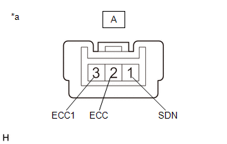
*a | Component without harness connected
(Shift Paddle Switch LH (No. 1 Transmission Shift Switch Assembly)) | | |
(b) Measure the resistance according to the value(s) in the table below.
Standard Resistance: |
Tester Connection | Condition |
Specified Condition | |
A-1 (SDN) - A-2 (ECC) |
"-" (Down shift) shift paddle switch operated and held |
Below 13 Ω | |
"-" (Down shift) shift paddle switch not operated |
10 kΩ or higher | |
A-1 (SDN) - A-3 (ECC1) |
"-" (Down shift) shift paddle switch operated and held |
Below 13 Ω | |
"-" (Down shift) shift paddle switch not operated |
10 kΩ or higher |
| NG |
| REPLACE SHIFT PADDLE SWITCH LH (NO. 1 TRANSMISSION SHIFT SWITCH ASSEMBLY) |
|
OK | |
| |
| 7. |
INSPECT SHIFT PADDLE SWITCH RH (NO. 2 TRANSMISSION SHIFT SWITCH ASSEMBLY) |
| (a) Remove the shift paddle switch RH (No. 2 transmission shift switch assembly).
Click here |
 |
|
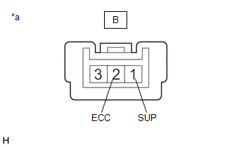
*a | Component without harness connected
(Shift Paddle Switch RH (No. 2 Transmission Shift Switch Assembly)) | | |
(b) Measure the resistance according to the value(s) in the table below.
Standard Resistance: |
Tester Connection | Condition |
Specified Condition | |
B-1 (SUP) - B-2 (ECC) |
"+" (Up shift) shift paddle switch operated and held |
Below 13 Ω | |
"+" (Up shift) shift paddle switch not operated |
10 kΩ or higher |
| NG |
| REPLACE SHIFT PADDLE SWITCH RH (NO. 2 TRANSMISSION SHIFT SWITCH ASSEMBLY) |
|
OK | |
| |
| 8. |
INSPECT NO. 1 SWITCH WIRE |
| (a) Install the No. 1 and No. 2 transmission shift switch assemblies.
Click here |
 |
|
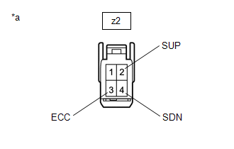
*a | Front view of wire harness connector
(to Spiral Cable Sub-assembly) | | |
(b) Disconnect the z2 No. 1 switch wire connector. (c) Measure the resistance according to the value(s) in the table below.
Standard Resistance: |
Tester Connection | Condition |
Specified Condition | |
z2-2 (SUP) - z2-3 (ECC) |
"+" (Up shift) shift paddle switch operated and held |
Below 13 Ω | |
"+" (Up shift) shift paddle switch not operated |
10 kΩ or higher | |
z2-4 (SDN) - z2-3 (ECC) |
"-" (Down shift) shift paddle switch operated and held |
Below 13 Ω | |
"-" (Down shift) shift paddle switch not operated |
10 kΩ or higher |
| OK |
| PROCEED TO NEXT SUSPECTED AREA SHOWN IN PROBLEM SYMPTOMS TABLE |
| NG |
| REPLACE NO. 1 SWITCH WIRE | | 

