ON-VEHICLE INSPECTION CAUTION / NOTICE / HINT CAUTION: To prevent injury due to contact with an operating V-ribbed belt or cooling fan, keep your hands and clothing away from the V-ribbed belt and cooling fans when working in the engine compartment with the engine running or the engine switch on (IG). 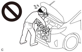 PROCEDURE 1. INSPECT FUEL CUT OPERATION CAUTION: To prevent injury due to contact with an operating V-ribbed belt or cooling fan, keep your hands and clothing away from the V-ribbed belt and cooling fans when working in the engine compartment with the engine running or the engine switch on (IG). (a) Start the engine. (b) Warm up the engine. (c) Increase the engine speed to approximately 3500 rpm. (d) Use a sound scope to check for fuel injector assembly operating sounds. (e) When the accelerator pedal is fully released, check that fuel injector assembly operating sounds stop momentarily and then resume. Standard:
If the result is not as specified, check the fuel injector assemblies, wire harness and ECM. 2. VISUALLY CHECK HOSES, CONNECTIONS AND GASKETS (a) Visually check that the hoses, connections and gaskets have no cracks, leaks or damage. NOTICE:
If any defects are found, replace parts as necessary. 3. INSPECT EVAPORATIVE EMISSION CONTROL SYSTEM CAUTION: To prevent injury due to contact with an operating V-ribbed belt or cooling fan, keep your hands and clothing away from the V-ribbed belt and cooling fans when working in the engine compartment with the engine running or the engine switch on (IG). (a) Connect the Techstream to the DLC3. (b) Start the engine. (c) Turn the Techstream on.
(e) Enter the following menus: Powertrain / Engine / Active Test / Activate the EVAP Purge VSV. Powertrain > Engine > Active Test
(f) Check that vacuum occurs at the purge valve (purge VSV) port. (g) If vacuum does not occur, check the following items.
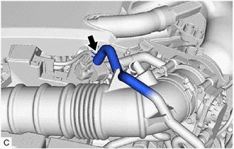
(h) Exit Active Test mode and connect the fuel vapor feed hose to the purge valve (purge VSV) and slide the clip to secure it. If the result is not as specified, replace the purge valve (purge VSV), wire harness or ECM. Click here (i) Enter the following menus: Powertrain / Engine / Data List / EVAP (Purge) VSV. Powertrain > Engine > Data List
(j) Warm up the engine and drive the vehicle. (k) Confirm that the purge valve (purge VSV) opens. If the result is not as specified, replace the purge valve (purge VSV), wire harness or ECM. 4. CHECK FUEL TANK AND VENT LINE (a) Disconnect the fuel tank vent hose from the canister (charcoal canister assembly). 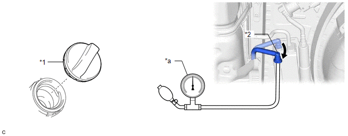
(b) Connect a pressure gauge to the fuel tank vent hose. (c) Apply 4 kPa (0.04 kgf/cm2, 0.6 psi) of pressure to the vent line of the fuel tank assembly. HINT: Perform this inspection with the fuel tank assembly less than 90% full. When the fuel tank assembly is full, the fuel fill check valve closes and the pressure is released through the 2 mm (0.0787 in.) orifice. As a result, when the fuel tank cap assembly is removed, the pressure does not decrease smoothly. (d) Check that the fuel tank assembly pressure is maintained for some time and does not decrease immediately. HINT: If the pressure decreases immediately, one of the following may apply:
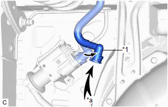
(e) Remove the fuel tank cap assembly and check that the pressure is released smoothly. If the pressure is not released smoothly, replace the fuel tank assembly. (f) Connect the fuel tank vent hose to the canister (charcoal canister assembly). 5. INSPECT AIR LINE
(b) Check that air flows freely into the air line. If air does not flow freely into the air line, repair or replace the air line tube. (c) Connect the air line tube to the leak detection pump sub-assembly. |
Toyota Avalon (XX50) 2019-2022 Service & Repair Manual > Intelligent Clearance Sonar System(for Gasoline Model): Vehicle Information Unmatched (C168D)
DESCRIPTION If the vehicle information stored in the main body ECU (multiplex network body ECU) which is sent via CAN communication during the clearance warning ECU assembly self-diagnosis does not match that of clearance warning ECU assembly, DTC C168D is stored. DTC No. Detection Item DTC Detectio ...