Components COMPONENTS ILLUSTRATION 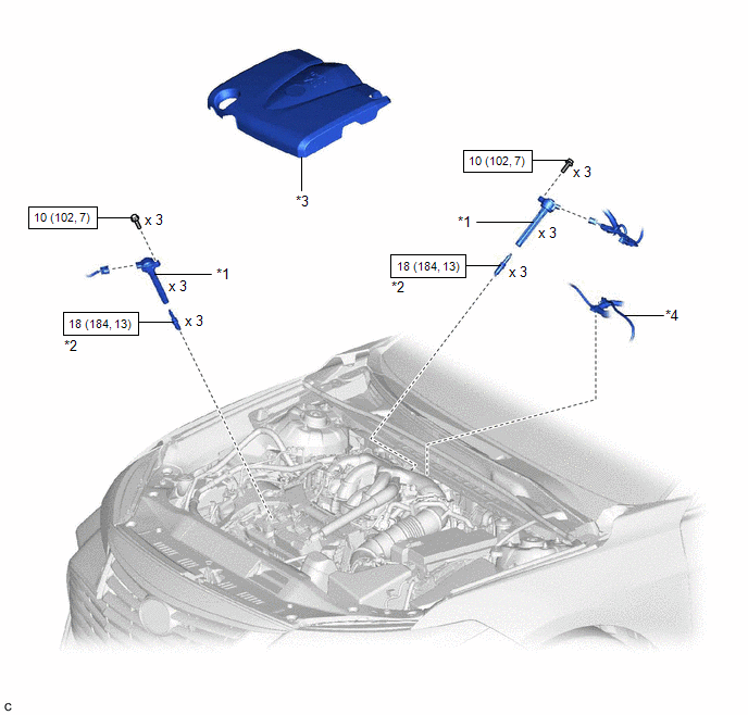
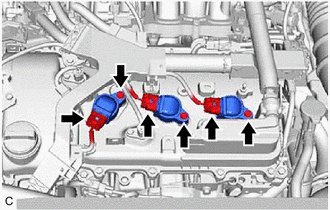
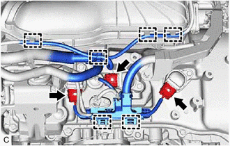
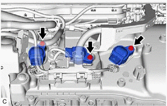
Installation INSTALLATION PROCEDURE 1. INSTALL SPARK PLUG Click here 2. INSTALL IGNITION COIL ASSEMBLY HINT: Perform "Inspection After Repair" after replacing an ignition coil assembly. Click here (a) Install the 3 ignition coil assemblies to the cylinder head cover sub-assembly with the 3 bolts. Torque: 10 N·m {102 kgf·cm, 7 ft·lbf} NOTICE: If an ignition coil assembly has been struck or dropped, replace it. HINT: Install the same parts to their original positions. (b) Connect the 3 ignition coil assembly connectors. (c) Engage the 2 wire harness clamps. (d) Engage the 4 clamps to install the vacuum hose to the intake air surge tank assembly. (e) Install the 3 ignition coil assemblies to the cylinder head cover sub-assembly LH with the 3 bolts. Torque: 10 N·m {102 kgf·cm, 7 ft·lbf} NOTICE: If an ignition coil assembly has been struck or dropped, replace it. HINT: Install the same parts to their original positions. (f) Connect the 3 ignition coil assembly connectors. 3. INSTALL V-BANK COVER SUB-ASSEMBLY Click here
4. PERFORM INITIALIZATION (a) Perform "Inspection After Repair" after replacing an ignition coil assembly or spark plug. Click here Removal REMOVAL CAUTION / NOTICE / HINT The necessary procedures (adjustment, calibration, initialization, or registration) that must be performed after parts are removed and installed, or replaced during ignition coil assembly or spark plug removal/installation are shown below. Necessary Procedures After Parts Removed/Installed/Replaced
PROCEDURE 1. REMOVE V-BANK COVER SUB-ASSEMBLY Click here
2. REMOVE IGNITION COIL ASSEMBLY
(b) Remove the 3 bolts and 3 ignition coil assemblies from the cylinder head cover sub-assembly LH. NOTICE: If an ignition coil assembly has been struck or dropped, replace it. HINT: Arrange the removed parts in the correct order.
(d) Disengage the 2 wire harness clamps. (e) Disconnect the 3 ignition coil assembly connectors.
3. REMOVE SPARK PLUG Click here |
Toyota Avalon (XX50) 2019-2022 Service & Repair Manual > Blower Unit: Removal
REMOVAL CAUTION / NOTICE / HINT The necessary procedures (adjustment, calibration, initialization or registration) that must be performed after parts are removed and installed, or replaced during blower unit removal/installation are shown below. Necessary Procedure After Parts Removed/Installed/Repl ...