DESCRIPTION The mass air flow meter sub-assembly is a sensor that measures the intake air volume using the following built-in components:
Intake air flows past the temperature sensor (before heater), the heater, and then the temperature sensor (after heater) of the silicon chip sensor in the by-pass duct. As the intake air is warmed up when it is exposed to the heater, the temperature of the intake air as it flows past the temperature sensor (after heater) is higher than when it flows past the temperature sensor (before heater). The difference in temperature of the intake air at each temperature sensor varies depending on the velocity of the intake air that flows past the silicon chip sensor. The temperature sensor bridge circuit detects the difference in temperature and the control circuit converts it into a pulse signal and outputs it to the ECM. When the temperature detected by the temperature sensor (before heater) is higher than that detected by the temperature sensor (after heater), backflow of the intake air is detected. The ECM calculates the intake air volume based on the pulse signal received from the mass air flow meter sub-assembly, and uses it to determine the fuel injection duration necessary for an optimal air-fuel ratio. The heater control bridge circuit has a temperature sensor and power transistor, and maintains the heater temperature at a specific temperature. HINT: When DTCs is stored, the ECM enters fail-safe mode. During fail-safe mode, the ECM calculates the fuel injection duration based on the engine speed and throttle valve angle. Fail-safe mode continues until a pass condition is detected. 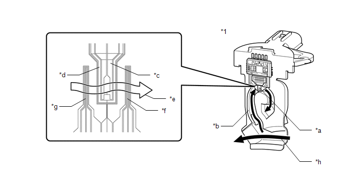
MONITOR DESCRIPTION If there is a defect or an open or short circuit in the mass air flow meter sub-assembly, the frequency level deviates from the normal operating range. The ECM interprets this deviation as a malfunction in the mass air flow meter sub-assembly circuit and stores a DTC. Example: When the sensor output frequency remains less than 0.1 kHz, or higher than 9.8 kHz for 3 seconds, the ECM stores a DTC. MONITOR STRATEGY
TYPICAL ENABLING CONDITIONS
TYPICAL MALFUNCTION THRESHOLDS P0102
CONFIRMATION DRIVING PATTERN HINT:
WIRING DIAGRAM 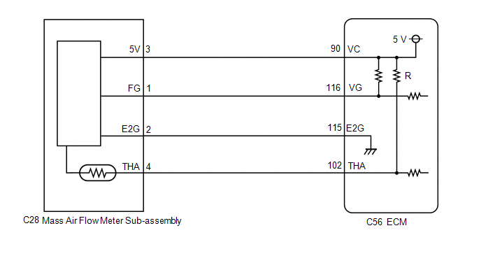 CAUTION / NOTICE / HINT HINT: Read freeze frame data using the Techstream. The ECM records vehicle and driving condition information as freeze frame data the moment a DTC is stored. When troubleshooting, freeze frame data can help determine if the vehicle was moving or stationary, if the engine was warmed up or not, if the air fuel ratio was lean or rich, and other data from the time the malfunction occurred. PROCEDURE
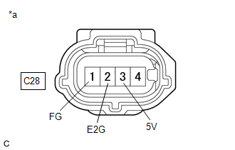
(a) Disconnect the mass air flow meter sub-assembly connector. (b) Turn the engine switch on (IG). (c) Measure the voltage according to the value(s) in the table below. Standard Voltage:
(a) Replace the mass air flow meter sub-assembly. Click here
HINT: Perform "Inspection After Repair" after replacing the mass air flow meter sub-assembly. Click here
(a) Connect the Techstream to the DLC3. (b) Turn the engine switch on (IG). (c) Turn the Techstream on. (d) Clear the DTC. Powertrain > Engine > Clear DTCs(e) Turn the engine switch off and wait for at least 30 seconds.
(a) Drive the vehicle in accordance with the driving pattern described in Confirmation Driving Pattern. (b) Enter the following menus: Powertrain / Engine / Trouble Codes. (c) Read the DTCs. Powertrain > Engine > Trouble Codes
(a) Disconnect the mass air flow meter sub-assembly connector. (b) Disconnect the ECM connector. (c) Measure the resistance according to the value(s) in the table below. Standard Resistance:
|
Toyota Avalon (XX50) 2019-2022 Service & Repair Manual > Can Communication System(for Hv Model): Steering Angle Sensor Communication Stop Mode
DESCRIPTION Detection Item Symptom Trouble Area Steering Angle Sensor Communication Stop Mode Any of the following conditions are met: Communication stop for "Spiral cable (Steering Angle Sensor)" is indicated on the "Communication Bus Check" screen of the Techstream. Click here Communication stop h ...


