DESCRIPTION 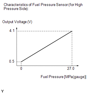 The fuel pressure sensor (for high pressure side) is installed on the fuel delivery pipe (for high pressure side). The fuel pressure sensor (for high pressure side) changes the fuel pressure for high pressure side into an electrical signal and sends the signal to the ECM. Then the ECM controls the pump discharge using this feedback to maintain the fuel's target pressure between 2 and 25 MPa (20 and 255 kgf/cm2).
HINT: When this DTC is output, check the fuel pressure (for high pressure side) in the Data List. Enter the following menus: Powertrain / Engine / Data List / Fuel Pressure (High).
If the Data List values is normal it may be due to a temporary recovery from the malfunction condition. Check for intermittent problems. MONITOR DESCRIPTION This DTC is stored if the fuel pressure sensor (for high pressure side) output voltage is out of the standard range due to an open or short in the sensor circuit. Example: If the fuel pressure sensor (for high pressure side) output voltage is less than 0.2933 V for 3 seconds or more, the ECM store this DTC. MONITOR STRATEGY
TYPICAL ENABLING CONDITIONS
TYPICAL MALFUNCTION THRESHOLDS
CONFIRMATION DRIVING PATTERN HINT:
WIRING DIAGRAM 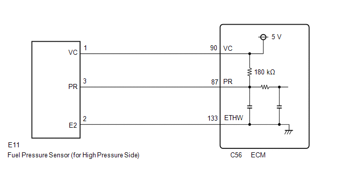 CAUTION / NOTICE / HINT HINT: Read freeze frame data using the Techstream. The ECM records vehicle and driving condition information as freeze frame data the moment a DTC is stored. When troubleshooting, freeze frame data can help determine if the vehicle was moving or stationary, if the engine was warmed up or not, if the air fuel ratio was lean or rich, and other data from the time the malfunction occurred. PROCEDURE
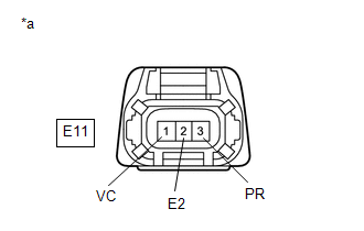
HINT: Make sure that the connector is properly connected. If it is not, securely connect it and check for DTCs again. (a) Disconnect the fuel pressure sensor (for high pressure side) connector. (b) Turn the engine switch on (IG). (c) Measure the voltage according to the value(s) in the table below. Standard Voltage:
(d) Turn the engine switch off and wait for at least 30 seconds. (e) Measure the resistance according to the value(s) in the table below. Standard Resistance:
HINT: Perform "Inspection After Repair" after replacing the fuel pressure sensor (for high pressure side). Click here
(a) Disconnect the fuel pressure sensor (for high pressure side) connector. (b) Disconnect the ECM connector. (c) Measure the resistance according to the value(s) in the table below. Standard Resistance:
|
Toyota Avalon (XX50) 2019-2022 Service & Repair Manual > Power Steering System(for Gasoline Model): Assist Map Number Mismatch (C1582)
DESCRIPTION When an incorrect ECM, main body ECU (multiplex network body ECU), skid control ECU (brake actuator assembly) or AVS ECU (Absorber control ECU) (w/ Adaptive Variable Suspension System) is installed after the assist map has been written to the power steering ECU (rack and pinion power ste ...


