DESCRIPTION The electronic throttle control system is composed of the throttle actuator, throttle position sensor, accelerator pedal position sensor, and ECM. The ECM operates the throttle actuator to regulate the throttle valve in response to driver inputs. The throttle position sensor detects the opening angle of the throttle valve, and provides the ECM with feedback so that the throttle valve can be appropriately controlled by the ECM.
MONITOR DESCRIPTION The ECM determines the actual opening angle of the throttle valve from the throttle position sensor signal. The actual opening angle is compared to the target opening angle commanded by the ECM. If the difference between these two values is outside the standard range, the ECM interprets this as a malfunction in the electronic throttle control system, illuminates the MIL and stores a DTC. MONITOR STRATEGY
TYPICAL ENABLING CONDITIONS
TYPICAL MALFUNCTION THRESHOLDS
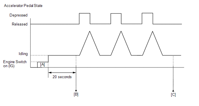
CONFIRMATION DRIVING PATTERN HINT:
FAIL-SAFE When any of these DTCs or other DTCs relating to Electronic Throttle Control System (ETCS) malfunctions are stored, the ECM enters fail-safe mode. During fail-safe mode, the ECM cuts the current to the throttle actuator, and the throttle valve is returned to a 7° throttle valve opening angle by the return spring. The ECM then adjusts the engine output by controlling the fuel injection (intermittent fuel-cut) and ignition timing, in accordance with the accelerator pedal opening angle, to allow the vehicle to continue running at a minimal speed. If the accelerator pedal is depressed firmly and gently, the vehicle can be driven slowly. Fail-safe mode continues until a pass condition is detected, and the engine switch is then turned off. WIRING DIAGRAM Refer to DTC P210014. Click here CAUTION / NOTICE / HINT HINT:
PROCEDURE
(a) Connect the Techstream to the DLC3. (b) Turn the engine switch on (IG). (c) Turn the Techstream on. (d) Enter the following menus: Powertrain / Engine / Trouble Codes. (e) Read the DTCs. Powertrain > Engine > Trouble Codes
HINT: If any DTCs other than P211900, P211904 or P211977 are output, troubleshoot those DTCs first.
(a) Connect the Techstream to the DLC3. (b) Turn the engine switch on (IG). (c) Turn the Techstream on. (d) Using the Techstream, confirm the vehicle conditions recorded in the freeze frame data which were present when the DTC was stored. Click here
for Intake Camshaft of Bank 1:
HINT: If *1 or *2 is applicable, the malfunction may be caused by Intake VVT System Bank 1 being over-retarded or over-advanced, so perform inspection following the procedures for DTC P001100 (Camshaft Position "A" - Timing Over-Advanced or System Performance Bank 1) and P001200 (Camshaft Position "A" - Timing Over-Retarded Bank 1). for Intake Camshaft of Bank 2:
HINT: If *3 or *4 is applicable, the malfunction may be caused by Intake VVT System Bank 2 being over-retarded or over-advanced, so perform inspection following the procedures for DTC P002100 (Camshaft Position "A" - Timing Over-Advanced or System Performance Bank 2) and P002200 (Camshaft Position "A" - Timing Over-Retarded Bank 2). for Exhaust Camshaft of Bank 1:
HINT: If *5 or *6 is applicable, the malfunction may be caused by Exhaust VVT System Bank 1 being over-retarded or over-advanced, so perform inspection following the procedures for DTC P001400 (Camshaft Position "B" - Timing Over-Advanced or System Performance Bank 1) and P001500 (Camshaft Position "B" - Timing Over-Retarded Bank 1). for Exhaust Camshaft of Bank 2:
HINT: If *7 or *8 is applicable, the malfunction may be caused by Exhaust VVT System Bank 2 being over-retarded or over-advanced, so perform inspection following the procedures for DTC P002400 (Camshaft Position "B" - Timing Over-Advanced or System Performance Bank 2) and P002500 (Camshaft Position "B" - Timing Over-Retarded Bank 2).
(a) Connect the Techstream to the DLC3. (b) Turn the engine switch on (IG). (c) Turn the Techstream on. (d) Clear the DTCs. Powertrain > Engine > Clear DTCs(e) Turn the engine switch off and wait for at least 30 seconds. (f) Start the engine. (g) Turn the Techstream on. (h) Enter the following menus: Powertrain / Engine / Data List / Throttle Position Sensor No.1 Voltage and Throttle Position Command. Powertrain > Engine > Data List
(i) Read the values displayed on the Techstream while fully depressing and releasing the accelerator pedal quickly.
HINT: When a DTC is output, the system changes to fail-safe mode. Therefore, only use the data up until the time the DTC is stored for confirmation.
(a) Inspect the throttle body with motor assembly. Click here
(a) Check for contamination between the throttle valve and housing. If necessary, clean the throttle body with motor assembly. Also, check that the throttle valve moves smoothly. OK: Throttle valve is not contaminated with foreign matter and moves smoothly. HINT: Perform "Inspection After Repair" after cleaning the throttle body with motor assembly. Click here
(a) Connect the Techstream to the DLC3. (b) Turn the engine switch on (IG). (c) Turn the Techstream on. (d) Clear the DTCs. Powertrain > Engine > Clear DTCs(e) Turn the engine switch off and wait for at least 30 seconds. (f) Turn the engine switch on (IG) and turn the Techstream on. (g) Enter the following menus: Powertrain / Engine / Data List / Throttle Position Sensor No.1 Voltage, Throttle Position Sensor No.2 Voltage and Throttle Position Command. Powertrain > Engine > Data List
(h) Read the values displayed on the Techstream while wiggling the ECM wire harness. (i) Enter the following menus: Powertrain / Engine / Trouble Codes. (j) Read the DTCs. Powertrain > Engine > Trouble Codes
(a) As the DTC was stored due to a change in the contact resistance of the connector, repair or replace the wire harness or connector. Click here
(a) Replace the throttle body with motor assembly. Click here
HINT: Perform "Inspection After Repair" after replacing the throttle body with motor assembly. Click here
(a) Connect the Techstream to the DLC3. (b) Turn the engine switch on (IG). (c) Turn the Techstream on. (d) Clear the DTC. Powertrain > Engine > Clear DTCs(e) Turn the engine switch off and wait for at least 30 seconds.
(a) Drive the vehicle in accordance with the driving pattern described in Confirmation Driving Pattern. (b) Enter the following menus: Powertrain / Engine / Trouble Codes. (c) Read the DTCs. Powertrain > Engine > Trouble Codes
|
Toyota Avalon (XX50) 2019-2022 Service & Repair Manual > Vehicle Proximity Notification System: Speaker Circuit (B1350)
DESCRIPTION The vehicle approaching speaker assembly circuit consists of the vehicle approaching speaker controller and vehicle approaching speaker assembly. This DTC is stored when a malfunction is detected in the vehicle approaching speaker assembly circuit. DTC No. Detection Item DTC Detection Co ...


