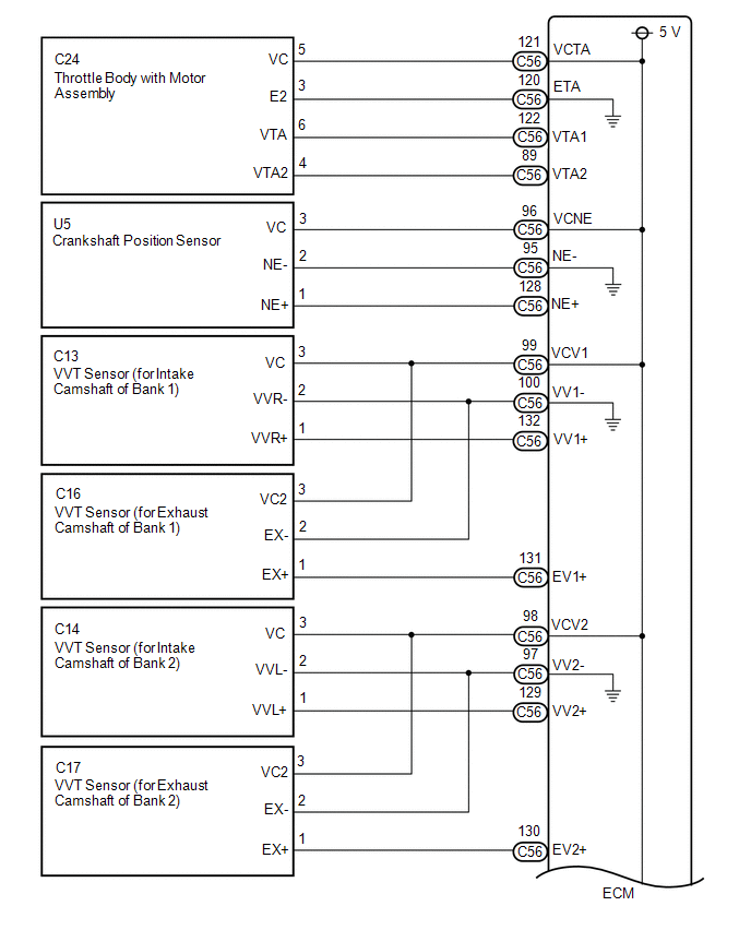
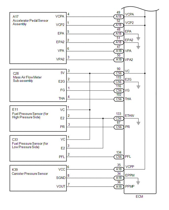
DESCRIPTION The ECM constantly generates a 5 V power source voltage from the battery voltage supplied to the +B, +B2 (BATT) terminals to operate the microprocessor. The ECM also provides this power to the sensors through the VC output circuit. 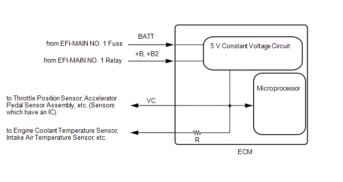 When the VC circuit has a short circuit, the microprocessor in the ECM and sensors that are supplied power through the VC circuit are deactivated because power is not supplied from the VC circuit. When the system is in this condition, it will not start. WIRING DIAGRAM
CAUTION / NOTICE / HINT NOTICE: Check the fuses for circuits related to this system before performing the following inspection procedure. PROCEDURE
(a) Connect the Techstream to the DLC3. (b) Turn the engine switch on (IG). (c) Turn the Techstream on. (d) Check the communication between the Techstream and ECM. HINT: It can be checked using the "Engine" item of the Data List.
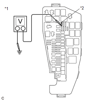
(a) Turn the engine switch on (IG). (b) Measure the voltage according to the value(s) in the table below. Standard Voltage:
HINT:
(a) Disconnect the throttle body with motor assembly connector. (b) Turn the engine switch on (IG). (c) Turn the Techstream on. (d) Check the communication between the Techstream and ECM. HINT: It can be checked using the "Engine" item of the Data List.
HINT: Perform "Inspection After Repair" after replacing the throttle body with motor assembly. Click here
(a) Disconnect the accelerator pedal sensor assembly connector. (b) Turn the engine switch on (IG). (c) Turn the Techstream on. (d) Check the communication between the Techstream and ECM. HINT: It can be checked using the "Engine" item of the Data List.
(a) Disconnect the crankshaft position sensor connector. (b) Turn the engine switch on (IG). (c) Turn the Techstream on. (d) Check the communication between the Techstream and ECM. HINT: It can be checked using the "Engine" item of the Data List.
(a) Disconnect the VVT sensor (for intake camshaft of bank 1) connector. (b) Turn the engine switch on (IG). (c) Turn the Techstream on. (d) Check the communication between the Techstream and ECM. HINT: It can be checked using the "Engine" item of the Data List.
(a) Disconnect the VVT sensor (for intake camshaft of bank 2) connector. (b) Turn the engine switch on (IG). (c) Turn the Techstream on. (d) Check the communication between the Techstream and ECM. HINT: It can be checked using the "Engine" item of the Data List.
(a) Disconnect the VVT sensor (for exhaust camshaft of bank 1) connector. (b) Turn the engine switch on (IG). (c) Turn the Techstream on. (d) Check the communication between the Techstream and ECM. HINT: It can be checked using the "Engine" item of the Data List.
(a) Disconnect the VVT sensor (for exhaust camshaft of bank 2) connector. (b) Turn the engine switch on (IG). (c) Turn the Techstream on. (d) Check the communication between the Techstream and ECM. HINT: It can be checked using the "Engine" item of the Data List.
(a) Disconnect the fuel pressure sensor (for high pressure side) connector. (b) Turn the engine switch on (IG). (c) Turn the Techstream on. (d) Check the communication between the Techstream and ECM. HINT: It can be checked using the "Engine" item of the Data List.
HINT: Perform "Inspection After Repair" after replacing the fuel pressure sensor (for high pressure side). Click here
(a) Disconnect the fuel pressure sensor (for low pressure side) connector. (b) Turn the engine switch on (IG). (c) Turn the Techstream on. (d) Check the communication between the Techstream and ECM. HINT: It can be checked using the "Engine" item of the Data List.
HINT: Perform "Inspection After Repair" after replacing the fuel pressure sensor (for low pressure side). Click here
(a) Disconnect the mass air flow meter sub-assembly connector. (b) Turn the engine switch on (IG). (c) Turn the Techstream on. (d) Check the communication between the Techstream and ECM. HINT: It can be checked using the "Engine" item of the Data List.
(a) Disconnect the canister pump module connector. (b) Turn the engine switch on (IG). (c) Turn the Techstream on. (d) Check the communication between the Techstream and ECM. HINT: It can be checked using the "Engine" item of the Data List.
(a) Disconnect the throttle body with motor assembly connector. (b) Disconnect the accelerator pedal sensor assembly connector. (c) Disconnect the crankshaft position sensor connector. (d) Disconnect the VVT sensor (for intake camshaft of bank 1) connector. (e) Disconnect the VVT sensor (for intake camshaft of bank 2) connector. (f) Disconnect the VVT sensor (for exhaust camshaft of bank 1) connector. (g) Disconnect the VVT sensor (for exhaust camshaft of bank 2) connector. (h) Disconnect the fuel pressure sensor (for high pressure side) connector. (i) Disconnect the fuel pressure sensor (for low pressure side) connector. (j) Disconnect the mass air flow meter sub-assembly connector. (k) Disconnect the ECM connectors. (l) Disconnect the canister pump module connector. (m) Measure the resistance according to the value(s) in the table below. Standard Resistance:
(n) Measure the resistance according to the value(s) in the table below. HINT: Remove the EFI-MAIN NO. 2 and EFI-MAIN NO. 3 relays connected between the checked terminals as the coil inside the relay influences the measurement value. Standard Resistance:
|
Toyota Avalon (XX50) 2019-2022 Service & Repair Manual > General Maintenance: Under Hood
UNDER HOOD GENERAL NOTES Maintenance requirements vary depending on country. Check the maintenance schedule in the owner's manual. Following the maintenance schedule is mandatory. Determine the appropriate time to service the vehicle using either miles driven or time (months) elapsed, whichever reac ...