INSTALLATION PROCEDURE 1. TEMPORARILY INSTALL FUEL PUMP ASSEMBLY
(b) Fill the fuel pump lifter housing oil collection areas with 30 cc (1.8 cu. in.) of engine oil from the fuel pump assembly hole of the cylinder head cover sub-assembly.
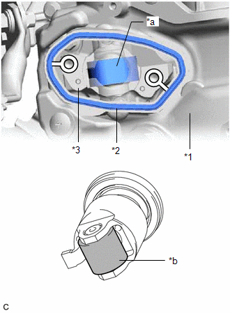
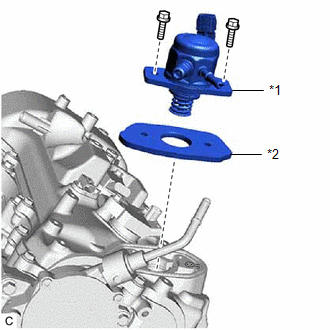
(d) Install a new fuel pump spacer gasket to the cylinder head cover sub-assembly.
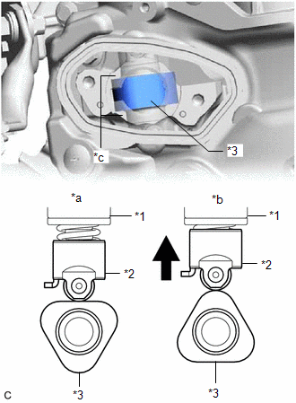
(f) Set the fuel pump lifter assembly on the fuel pump lifter housing as shown in the illustration. HINT: Align the stopper key of the fuel pump lifter assembly with the key groove of the fuel pump lifter housing. (g) Apply engine oil to a new O-ring and install it to the fuel pump assembly. NOTICE: Do not damage the O-ring.
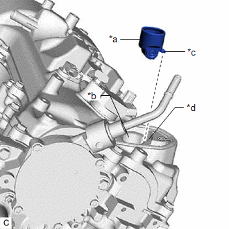
(i) Temporarily install the fuel pump assembly with the 2 bolts, leaving some allowance for left and right movement. 2. TEMPORARILY INSTALL NO. 1 FUEL PIPE SUB-ASSEMBLY NOTICE: Do not damage the seals of the union nuts of the No. 1 fuel pipe sub-assembly. (a) Temporarily install the No. 1 fuel pipe sub-assembly to the fuel delivery pipe RH and tighten the union nut by hand. (b) Temporarily install the No. 1 fuel pipe sub-assembly to the fuel pump assembly and tighten the union nut by hand. 3. INSTALL FUEL PUMP ASSEMBLY HINT: Perform "Inspection After Repair" after replacing the fuel pump assembly. Click here (a) Tighten the 2 bolts. Torque: 26 N·m {265 kgf·cm, 19 ft·lbf} (b) Connect the fuel pump assembly connector. 4. INSTALL NO. 1 FUEL PIPE SUB-ASSEMBLY
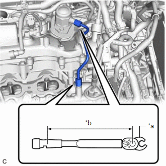
(b) Using a 17 mm union nut wrench, tighten the union nut on the fuel delivery pipe RH side of the No. 1 fuel pipe sub-assembly. Torque: Specified tightening torque : 35 N·m {357 kgf·cm, 26 ft·lbf} NOTICE: Do not adjust the torque in the loosening direction. HINT:
5. CONNECT NO. 2 FUEL TUBE SUB-ASSEMBLY (a) Connect the No. 2 fuel tube sub-assembly to the fuel pump assembly. Click here 6. INSTALL FUEL PUMP PROTECTOR (a) Install the fuel pump protector to the cylinder head sub-assembly with the 2 bolts. Torque: 21 N·m {214 kgf·cm, 15 ft·lbf} (b) Engage the clamp to connect the fuel tube sub-assembly to the fuel pump protector. 7. INSTALL INTAKE MANIFOLD Click here 8. CONNECT CABLE TO NEGATIVE BATTERY TERMINAL Click here
9. INSPECT FOR FUEL LEAK Click here
10. PERFORM INITIALIZATION (a) Perform "Inspection After Repair" after replacing the fuel pump assembly. Click here |
Toyota Avalon (XX50) 2019-2022 Service & Repair Manual > Lane Departure Alert System (w/ Steering Control)(for Hv Model): Yaw Rate Sensor Circuit (C1AA4,C1AA5)
DESCRIPTION The forward recognition camera receives vehicle stability signals from the yaw rate sensor (airbag ECU assembly). If the yaw rate sensor (airbag ECU assembly) detects an abnormal yaw rate sensor signal or yaw rate sensor power supply voltage, it informs the forward recognition camera via ...