REMOVAL CAUTION / NOTICE / HINT The necessary procedures (adjustment, calibration, initialization or registration) that must be performed after parts are removed and installed, or replaced during front exhaust pipe assembly (TWC: Rear Catalyst), center exhaust pipe assembly and tail exhaust pipe assembly removal/installation are shown below. Necessary Procedures After Parts Removed/Installed/Replaced
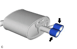
CAUTION: To prevent burns, do not touch the engine, exhaust pipe or other high temperature components while the engine is hot. 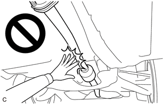 PROCEDURE 1. REMOVE TAIL EXHAUST PIPE ASSEMBLY CAUTION: To prevent burns, do not touch the engine, exhaust pipe or other high temperature components while the engine is hot.
(b) Remove the tail exhaust pipe assembly from the 2 exhaust pipe supports. (c) Remove the gasket from the center exhaust pipe assembly. 2. REMOVE TAIL EXHAUST PIPE ASSEMBLY LH CAUTION: To prevent burns, do not touch the engine, exhaust pipe or other high temperature components while the engine is hot.
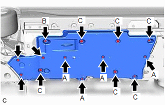
(b) Remove the tail exhaust pipe assembly LH from the 2 exhaust pipe supports. (c) Remove the gasket from the center exhaust pipe assembly. 3. REMOVE FRONT FLOOR COVER LH
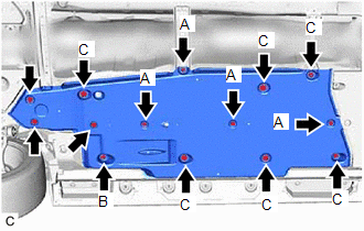
(b) Disengage the grommet (B) and 6 clips (C) to remove the front floor cover LH. 4. REMOVE FRONT FLOOR COVER RH
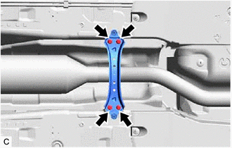
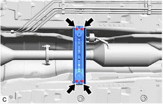
(b) Disengage the grommet (B) and 6 clips (C) to remove the front floor cover RH. 5. REMOVE FRONT CENTER FLOOR BRACE
6. REMOVE CENTER FLOOR CROSSMEMBER BRACE
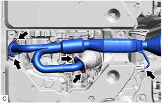
7. REMOVE CENTER EXHAUST PIPE ASSEMBLY CAUTION: To prevent burns, do not touch the engine, exhaust pipe or other high temperature components while the engine is hot.
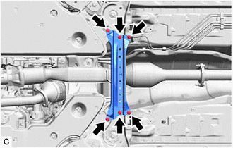
(b) Remove the center exhaust pipe assembly from the 2 exhaust pipe supports. (c) Remove the gasket from the front exhaust pipe assembly (TWC: Rear Catalyst). 8. REMOVE BODY MOUNTING PLATE
9. REMOVE NO. 1 EXHAUST PIPE SUPPORT BRACKET (for Lower Side)
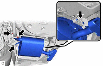
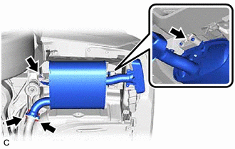
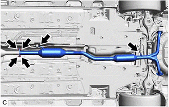
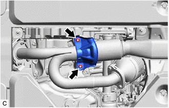
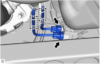
10. REMOVE FRONT EXHAUST PIPE ASSEMBLY (TWC: Rear Catalyst) CAUTION: To prevent burns, do not touch the engine, exhaust pipe or other high temperature components while the engine is hot.
(b) Disengage the 2 wire harness clamps.
(d) Remove the front exhaust pipe assembly (TWC: Rear Catalyst) from the exhaust pipe support. (e) Remove the 2 gaskets from the front exhaust pipe assembly (TWC: Rear Catalyst). 11. REMOVE HEATED OXYGEN SENSOR (for Bank 1) Click here
12. REMOVE HEATED OXYGEN SENSOR (for Bank 2) Click here 13. REMOVE TAIL PIPE BAFFLE (for Type B) HINT:
|
Toyota Avalon (XX50) 2019-2022 Service & Repair Manual > Sliding Roof System(for Gasoline Model): Sliding Roof does not Move by Operating Sliding Roof Control Switch
DESCRIPTION The sliding roof ECU (sliding roof drive gear assembly) receives slide and tilt signals and operates its built-in motor when the sliding roof switch (roof console box sub-assembly) is operated. WIRING DIAGRAM CAUTION / NOTICE / HINT NOTICE: Inspect the fuses for circuits related to this ...