Components COMPONENTS ILLUSTRATION 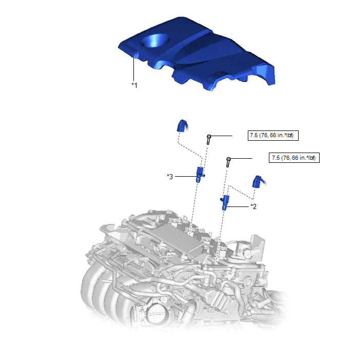
Installation INSTALLATION CAUTION / NOTICE / HINT NOTICE: This procedure includes the installation of small-head bolts. Refer to Small-Head Bolts of Basic Repair Hint to identify the small-head bolts. Click here
PROCEDURE 1. INSTALL CAMSHAFT POSITION SENSOR (for Exhaust Side) (a) Apply a light coat of engine oil to the O-ring of the camshaft position sensor. NOTICE: If reusing the camshaft position sensor, be sure to inspect the O-ring. (b) Using an 8 mm socket wrench, install the camshaft position sensor to the cylinder head cover sub-assembly with a new bolt. Torque: 7.5 N·m {76 kgf·cm, 66 in·lbf} NOTICE:
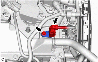
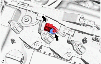
(c) Connect the camshaft position sensor connector. 2. INSTALL CAMSHAFT POSITION SENSOR (for Intake Side) (a) Apply a light coat of engine oil to the O-ring of the camshaft position sensor. NOTICE: If reusing the camshaft position sensor, be sure to inspect the O-ring. (b) Using an 8 mm socket wrench, install the camshaft position sensor to the cylinder head cover sub-assembly with a new bolt. Torque: 7.5 N·m {76 kgf·cm, 66 in·lbf} NOTICE:
(c) Connect the camshaft position sensor connector. 3. INSPECT FOR ENGINE OIL LEAK Click here 4. INSTALL NO. 1 ENGINE COVER SUB-ASSEMBLY Click here Removal REMOVAL CAUTION / NOTICE / HINT NOTICE: This procedure includes the removal of small-head bolts. Refer to Small-Head Bolts of Basic Repair Hint to identify the small-head bolts. Click here
PROCEDURE 1. REMOVE NO. 1 ENGINE COVER SUB-ASSEMBLY Click here 2. REMOVE CAMSHAFT POSITION SENSOR (for Intake Side)
(b) Using an 8 mm socket wrench, remove the bolt and camshaft position sensor from the cylinder head cover sub-assembly. NOTICE: If the camshaft position sensor has been struck or dropped, replace it. 3. REMOVE CAMSHAFT POSITION SENSOR (for Exhaust Side) (a) Disconnect the camshaft position sensor connector.
|
Toyota Avalon (XX50) 2019-2022 Service & Repair Manual > Safety Connect System(for Hv Model): Green Indicator Remains Off
DESCRIPTION After turning the power switch on (IG), the DCM (Telematics Transceiver) will enter into self check mode. The manual (SOS) switch red indicator will illuminate for 2 seconds and turn off followed by the manual (SOS) switch green indicator illuminating and remaining on under normal operat ...