Components COMPONENTS ILLUSTRATION 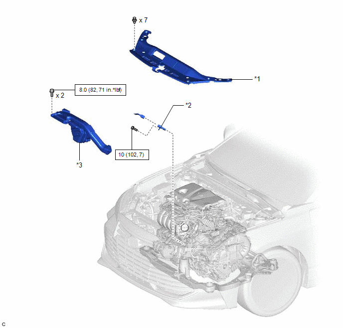
Installation INSTALLATION CAUTION / NOTICE / HINT NOTICE: This procedure includes the installation of small-head bolts. Refer to Small-Head Bolts of Basic Repair Hint to identify the small-head bolts. Click here
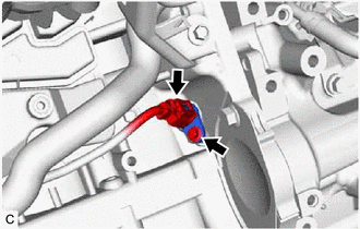
PROCEDURE 1. INSTALL CRANKSHAFT POSITION SENSOR (a) Apply a light coat of engine oil to the O-ring of the crankshaft position sensor. NOTICE: If reusing the crankshaft position sensor, be sure to inspect the O-ring. (b) Using an 8 mm socket wrench, install the crankshaft position sensor to the cylinder block sub-assembly with the bolt. Torque: 10 N·m {102 kgf·cm, 7 ft·lbf} NOTICE:
(c) Connect the crankshaft position sensor connector. 2. INSTALL INLET AIR CLEANER ASSEMBLY Click here 3. INSTALL COOL AIR INTAKE DUCT SEAL Click here Removal REMOVAL CAUTION / NOTICE / HINT NOTICE: This procedure includes the removal of small-head bolts. Refer to Small-Head Bolts of Basic Repair Hint to identify the small-head bolts. Click here
PROCEDURE 1. REMOVE COOL AIR INTAKE DUCT SEAL Click here 2. REMOVE INLET AIR CLEANER ASSEMBLY Click here 3. REMOVE CRANKSHAFT POSITION SENSOR
(b) Using an 8 mm socket wrench, remove the bolt and crankshaft position sensor from the cylinder block sub-assembly. NOTICE: If the crankshaft position sensor has been struck or dropped, replace it. |
Toyota Avalon (XX50) 2019-2022 Service & Repair Manual > Toyota Entune System(for Gasoline Model): Does not Recognize Voice Commands Performed to Contact Support Center
PROCEDURE 1. CHECK COMMUNICATION BASED VOICE RECOGNITION FUNCTION (a) While paying attention to the condition of the spoken voice command, say "Find a gas station in New York" and check that voice recognition is operating normally. HINT: When the voice command is recognized, the content of the voice ...