Toyota Avalon (XX50) 2019-2022 Service & Repair Manual: Ignition Circuit

DESCRIPTION

A direct ignition system is used on this vehicle. The direct ignition system is a 1 cylinder ignition system which ignites one cylinder with one ignition coil. In the 1 cylinder ignition system, one spark plug is connected to the end of the secondary winding. High voltage is generated in the secondary winding and is applied directly to the spark plug. The spark of the spark plug passes from the center electrode to the ground electrode.

The ECM determines the ignition timing and transmits the ignition signals for each cylinder. Using the ignition signal, the ECM turns on and off the power transistor inside the igniter, which switches on and off a current to the primary coil. When the current to the primary coil is cut off, high voltage is generated in the secondary coil and this voltage is applied to the spark plugs to create sparks inside the cylinders.

WIRING DIAGRAM

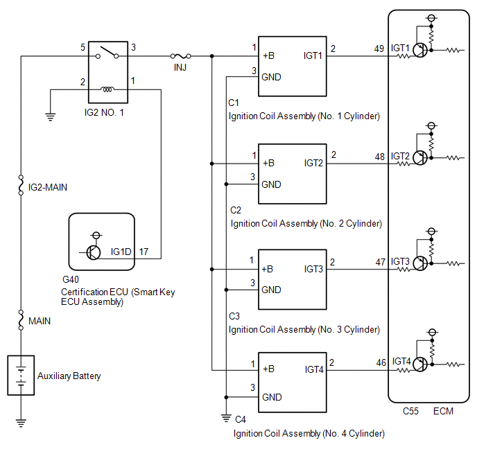
CAUTION / NOTICE / HINT

NOTICE:

Inspect the fuses for circuits related to this system before performing the following procedure.

HINT:

Perform a spark test before proceeding. If there is no spark for any cylinder, inspect this circuit.

Click here

PROCEDURE

1.

CHECK TERMINAL VOLTAGE (POWER SOURCE OF IGNITION COIL ASSEMBLY)

*a

Front view of wire harness connector

(to Ignition Coil Assembly)

(a) Disconnect the ignition coil assembly connectors.

(b) Turn the power switch on (IG).

(c) Measure the voltage according to the value(s) in the table below.

Standard Voltage:

Tester Connection

Condition

Specified Condition

C1-1 (+B) - C1-3 (GND)

Power switch on (IG)

11 to 14 V

C2-1 (+B) - C2-3 (GND)

Power switch on (IG)

11 to 14 V

C3-1 (+B) - C3-3 (GND)

Power switch on (IG)

11 to 14 V

C4-1 (+B) - C4-3 (GND)

Power switch on (IG)

11 to 14 V

NG

GO TO STEP 3

OK

2.

CHECK HARNESS AND CONNECTOR (IGNITION COIL ASSEMBLY - ECM)

(a) Disconnect the ignition coil assembly connectors.

(b) Disconnect the ECM connector.

(c) Measure the resistance according to the value(s) in the table below.

Standard Resistance:

Tester Connection

Condition

Specified Condition

C1-2 (IGT1) - C55-49 (IGT1)

Always

Below 1 Ω

C2-2 (IGT2) - C55-48 (IGT2)

Always

Below 1 Ω

C3-2 (IGT3) - C55-47 (IGT3)

Always

Below 1 Ω

C4-2 (IGT4) - C55-46 (IGT4)

Always

Below 1 Ω

C1-2 (IGT1) or C55-49 (IGT1) - Body ground and other terminals

Always

10 kΩ or higher

C2-2 (IGT2) or C55-48 (IGT2) - Body ground and other terminals

Always

10 kΩ or higher

C3-2 (IGT3) or C55-47 (IGT3) - Body ground and other terminals

Always

10 kΩ or higher

C4-2 (IGT4) or C55-46 (IGT4) - Body ground and other terminals

Always

10 kΩ or higher

OK

REPLACE ECM

NG

REPAIR OR REPLACE HARNESS OR CONNECTOR

3.

CHECK HARNESS AND CONNECTOR (IGNITION COIL ASSEMBLY - BODY GROUND)

(a) Disconnect the ignition coil assembly connectors.

(b) Measure the resistance according to the value(s) in the table below.

Standard Resistance:

Tester Connection

Condition

Specified Condition

C1-3 (GND) - Body ground

Always

Below 1 Ω

C2-3 (GND) - Body ground

Always

Below 1 Ω

C3-3 (GND) - Body ground

Always

Below 1 Ω

C4-3 (GND) - Body ground

Always

Below 1 Ω

NG

REPAIR OR REPLACE HARNESS OR CONNECTOR

OK

4.

CHECK HARNESS AND CONNECTOR (IG2 NO. 1 RELAY - IGNITION COIL ASSEMBLY)

(a) Disconnect the IG2 NO. 1 relay from No. 1 engine room relay block and No. 1 junction block assembly.

(b) Disconnect the ignition coil assembly connectors.

(c) Measure the resistance according to the value(s) in the table below.

Standard Resistance:

Tester Connection

Condition

Specified Condition

3 (IG2 NO. 1 relay) - C1-1 (+B)

Always

Below 1 Ω

3 (IG2 NO. 1 relay) - C2-1 (+B)

Always

Below 1 Ω

3 (IG2 NO. 1 relay) - C3-1 (+B)

Always

Below 1 Ω

3 (IG2 NO. 1 relay) - C4-1 (+B)

Always

Below 1 Ω

3 (IG2 NO. 1 relay) or C1-1 (+B) - Body ground and other terminals

Always

10 kΩ or higher

3 (IG2 NO. 1 relay) or C2-1 (+B) - Body ground and other terminals

Always

10 kΩ or higher

3 (IG2 NO. 1 relay) or C3-1 (+B) - Body ground and other terminals

Always

10 kΩ or higher

3 (IG2 NO. 1 relay) or C4-1 (+B) - Body ground and other terminals

Always

10 kΩ or higher

OK

GO TO ECM POWER SOURCE CIRCUIT

NG

REPAIR OR REPLACE HARNESS OR CONNECTOR

    How To Proceed With Troubleshooting

    Initialization

    See More:

    Toyota Avalon (XX50) 2019-2022 Service & Repair Manual > Electronically Controlled Brake System(for Hv Model): Malfunction in Rear Speed Sensor RH Circuit (C1403,C1404)
    DESCRIPTION Refer to DTCs C1415 and C1416. Click here DTC No. Detection Item INF Code DTC Detection Condition Trouble Area MIL Note C1403 Malfunction in Rear Speed Sensor RH Circuit 521 522 527 INF Code: 521 At a vehicle speed of 10 km/h (6 mph) or more, output voltage from one of the speed sensors ...

    Toyota Avalon (XX50) 2019-2022 Owners Manual

    Toyota Avalon (XX50) 2019-2022 Service & Repair Manual

    © 2024 Copyright www.tavalon.net
    0.0177