DTC SUMMARY |
DTC No. | Detection Item |
DTC Detection Condition | Trouble Area |
MIL | Memory |
Note | | P043E00 |
Evaporative Emission System Leak Detection Reference Orifice Low Flow |
Reference orifice detected as clogged during key-off EVAP monitor. |
- Canister pump module
- Connector/wire harness (Canister pump module - ECM)
- EVAP system hose (pipe from air inlet port to canister pump module, canister filter, fuel tank vent hose)
- ECM
| Comes on |
DTC stored | SAE Code: P043E | |
P043F00 | Evaporative Emission System Leak Detection Reference Orifice High Flow |
Reference orifice flow high during key-off EVAP monitor. |
- Canister pump module
- Connector/wire harness (Canister pump module - ECM)
- EVAP system hose (pipe from air inlet port to canister pump module, canister filter, fuel tank vent hose)
- ECM
| Comes on |
DTC stored | SAE Code: P043F | |
P24007E | Evaporative Emission System Leak Detection Pump Control Circuit Actuator Stuck On |
Leak detection pump on malfunction detected during key-off EVAP monitor. |
- Canister pump module
- Connector/wire harness (Canister pump module - ECM)
- EVAP system hose (pipe from air inlet port to canister pump module, canister filter, fuel tank vent hose)
- ECM
| Comes on |
DTC stored | SAE Code: P2402 | |
P24007F | Evaporative Emission System Leak Detection Pump Control Circuit Actuator Stuck Off |
Leak detection pump off malfunction detected during key-off EVAP monitor. |
- Canister pump module
- Connector/wire harness (Canister pump module - ECM)
- EVAP system hose (pipe from air inlet port to canister pump module, canister filter, fuel tank vent hose)
- ECM
| Comes on |
DTC stored | SAE Code: P2401 | |
P24187E | Evaporative Emission System Switching Valve Control Circuit Actuator Stuck On |
Vent valve on (closed) malfunction detected during key-off EVAP monitor. |
- Canister pump module
- Connector/wire harness (Canister pump module - ECM)
- EVAP system hose (pipe from air inlet port to canister pump module, canister filter, fuel tank vent hose)
- ECM
| Comes on |
DTC stored | SAE Code: P2419 |
HINT: The reference orifice is located inside the canister pump module. |
DTC No. | Monitoring Item |
Detection Timing | Detection Logic |
SAE Code | | P043E00 |
Reference orifice clogged |
EVAP monitoring (Power switch off) |
2 trip | P043E | |
P043F00 | Reference orifice high-flow |
P043F | | P24007E |
Leak detection pump stuck ON |
P2402 | | P24007F |
Leak detection pump stuck OFF |
P2401 | | P24187E |
Vent valve stuck closed |
P2419 | DESCRIPTION
Refer to EVAP (Evaporative Emission) System. Click here
 MONITOR DESCRIPTION
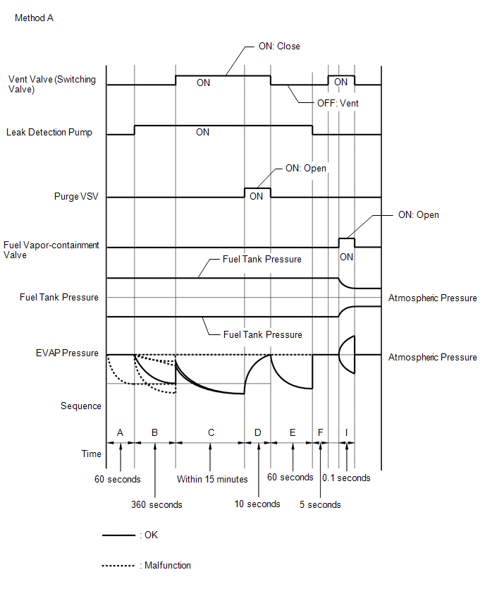
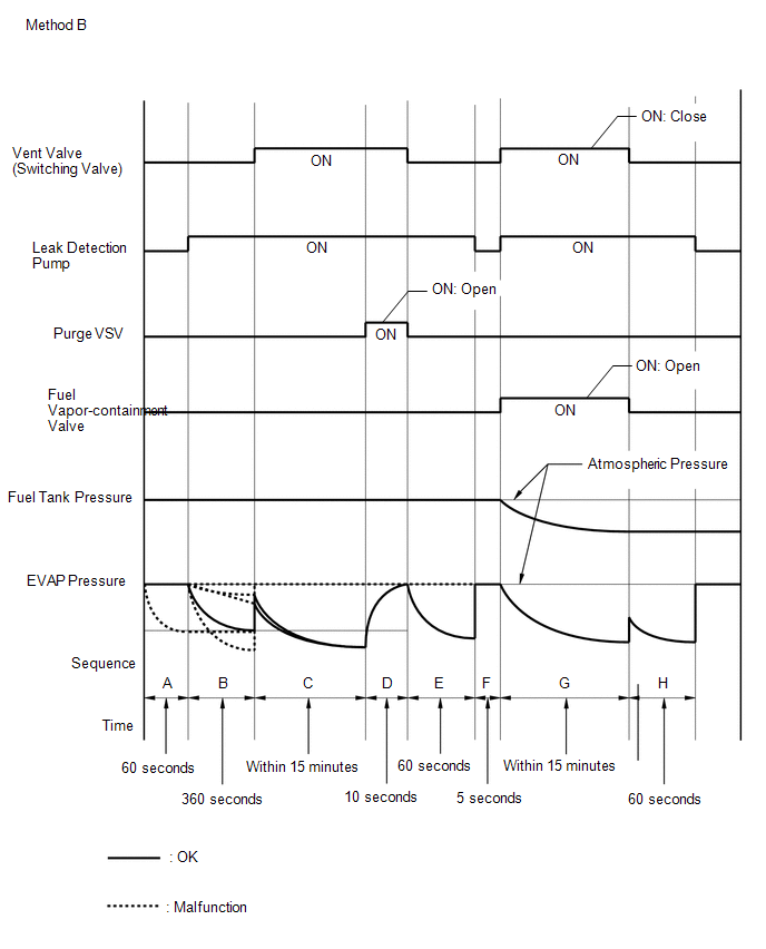
In
sequence B and E, the leak detection pump creates negative pressure
(vacuum) through the reference orifice. The EVAP system pressure is then
measured by the ECM, using the canister pressure sensor, to determine
the reference pressure. If the pressure detected meets one of the
following conditions, the ECM will illuminated the MIL and store a DTC
(2 trip detection logic).
- EVAP pressure is lower than the malfunction criterion.
- EVAP pressure is higher than the malfunction criterion.
- EVAP pressure is not saturated within 60 seconds.
- EVAP pressure difference between sequence B and E is large.
 MONITOR STRATEGY |
Required Sensors/Components (Main) | Canister pump module | |
Required Sensors/Components (Related) |
- | | Frequency of Operation |
Once per driving cycle | | Duration |
Within 7 minutes | | MIL Operation |
2 driving cycles | | Sequence of Operation |
None | TYPICAL ENABLING CONDITIONS |
Key-off monitor runs when all of the following conditions are met |
- | | Atmospheric pressure |
70 kPa(abs) [10.2 psi(abs)] or higher, and less than 110 kPa(abs) [16 psi(abs)] | |
Auxiliary battery voltage |
10.5 V or higher | |
Vehicle speed | Less than 4 km/h (2.5 mph) | |
Power switch | Off | |
Engine condition | Not running | |
Key-OFF duration | 5, 7 or 9.5 hours | |
Pressure sensor of canister pump module malfunction (P0451, P0452, P0453) |
Not detected | |
Fuel tank pressure sensor malfunction (P1451, P1452, P1453) |
Not detected | |
Purge VSV | Not operated by scan tool | |
Vent valve | Not operated by scan tool | |
Fuel vapor-containment valve |
Not operated by scan tool | |
Leak detection pump | Not operated by scan tool | |
Purge flow before key-OFF |
Performed | | Engine coolant temperature |
4.4°C (39.9°F) or higher, and less than 35°C (95°F) | |
Intake air temperature |
4.4°C (39.9°F) or higher, and less than 35°C (95°F) | TYPICAL MALFUNCTION THRESHOLDS |
One of following conditions met | - | |
EVAP pressure when 1.9 seconds after reference pressure measurement began |
Higher than -0.242 kPa(gauge) [-0.0351 psi(gauge)] | |
Reference pressure (vary with atmospheric pressure) |
Less than -4.85 kPa(gauge) [-0.7 psi(gauge)] | |
Reference pressure (vary with atmospheric pressure) |
-1.068 kPa(gauge) [-0.155 psi(gauge)] or higher | |
Reference pressure (vary with atmospheric pressure) |
Not saturated | | Reference pressure difference between the first and second |
0.9 kPa(gauge) [0.1 psi(gauge)] or higher | MONITOR RESULT
Refer to EVAP System. Click here CONFIRMATION DRIVING PATTERN
NOTICE:
- The Evaporative System Check (Automatic Mode) consists of 9 steps
performed automatically by the Techstream. It takes a maximum of
approximately 40 minutes.
- Do not perform the Evaporative System Check when the fuel tank is higher
than 90% full because the cut-off valve may be closed, making the fuel
tank leak check unavailable.
- Do not start the engine during this operation.
- When the temperature of the fuel is 35°C (95°F) or higher, a large
amount of vapor will from and any check result will be inaccurate. When
performing the Evaporative System Check, keep the fuel temperature less
than 35°C (95°F).
HINT:
- After repair has been completed, clear the DTC and then check that the
vehicle has returned to normal by performing the following All Readiness
check procedure.
Click here
- When clearing the permanent DTCs, refer to the "CLEAR PERMANENT DTC" procedure.
Click here
- Connect the Techstream to the DLC3.
- Turn the power switch on (IG).
- Turn the Techstream on.
- Clear the DTCs (even if no DTCs are stored, perform the clear DTC procedure).
- Turn the power switch off and wait for at least 30 seconds.
- Turn the power switch on (IG) [A].
- Turn the Techstream on.
- Enter the following menus: Powertrain / Engine / Utility / Evaporative System Check / Automatic Mode [B].
- After the "Evaporative System Check" is completed, check for All
Readiness by entering the following menus: Powertrain / Engine / Utility
/ All Readiness.
- Input the DTC: P043E00, P043F00, P24007E, P24007F or P24187E.
- Check the DTC judgment result.
|
Techstream Display |
Description |
|
NORMAL |
- DTC judgment completed
- System normal
|
|
ABNORMAL |
- DTC judgment completed
- System abnormal
|
|
INCOMPLETE |
- DTC judgment not completed
- Perform driving pattern after confirming DTC enabling conditions
|
HINT:
CAUTION / NOTICE / HINT
NOTICE:
PROCEDURE
(a) Refer to EVAP System. Click here
| NEXT |
 | END | |


