Toyota Avalon (XX50) 2019-2022 Service & Repair Manual: Mass or Volume Air Flow Sensor "A" Signal Plausibility Failure (P010064)

Toyota Avalon (XX50) 2019-2022 Service & Repair Manual / Engine / A25a-fxs Engine Control / Sfi System / Mass or Volume Air Flow Sensor "A" Signal Plausibility Failure (P010064)

DESCRIPTION

Refer to DTC P010012.

Click here

DTC No.

Detection Item

DTC Detection Condition

Trouble Area

MIL

Memory

Note

P010064

Mass or Volume Air Flow Sensor "A" Signal Plausibility Failure

All of the following conditions are met (2 trip detection logic).

  • The engine is running.
  • The engine coolant temperature is 70°C (158°F) or higher.
  • The throttle position sensor voltage is 0.2 V or higher, and less than 2 V.
  • Average engine load value ratio is less than 0.85, or higher than 1.15 (varies with estimated engine load).

    Average engine load value ratio = Average engine load based on mass air flow meter sub-assembly output / Average engine load estimated from driving conditions

  • Average air fuel ratio is less than -11%, or higher than 16%.
  • Mass air flow meter sub-assembly
  • Intake system
  • PCV hose connections
  • EGR valve assembly

Comes on

DTC stored

SAE Code: P0101

MONITOR DESCRIPTION

The mass air flow meter sub-assembly is a sensor that measures the amount of air flowing through the throttle valve. The ECM uses this information to determine fuel injection timing and to provide an appropriate air fuel ratio. Inside the mass air flow meter sub-assembly, there is a heated platinum wire which is exposed to the flow of intake air. By applying a specific electrical current to the wire, the ECM heats it to a specific temperature. The flow of incoming air cools both the wire and an internal thermistor, affecting their resistance. To maintain a constant current value, the ECM varies the voltage applied to the mass air flow meter sub-assembly. The voltage level is proportional to the airflow through the sensor, and the ECM uses it to calculate the intake air volume.

The ECM monitors the average engine load value ratio to check the mass air flow meter sub-assembly for malfunctions. The average engine load value ratio is obtained by comparing the average engine load calculated from the mass air flow meter sub-assembly output to the average engine load estimated from the driving conditions, such as the engine speed and the throttle opening angle. If the average engine load value ratio is below the threshold value, the ECM determines that the intake air volume is low, and if the average engine load value ratio is above the threshold value, the ECM determines that the intake air volume is high. If either of these conditions is detected in 2 consecutive driving cycles, the ECM illuminates the MIL and stores this DTC.

MONITOR STRATEGY

Related DTCs

P0101: Mass air flow meter rationality

Required Sensors/Components (Main)

Mass air flow meter sub-assembly

Required Sensors/Components (Related)

Crankshaft position sensor

Camshaft position sensor

Engine coolant temperature sensor

Throttle position sensor

Frequency of Operation

Continuous

Duration

10 times

MIL Operation

2 driving cycles

Sequence of Operation

None

TYPICAL ENABLING CONDITIONS

All of the following conditions are met

-

Throttle position voltage

0.2 V or higher, and less than 2 V

Time after engine start

5 seconds or more

Auxiliary battery voltage

10.5 V or higher

Engine coolant temperature

70°C (158°F) or higher

Estimated load

30% or higher, and less than 70%

Mass air flow meter circuit fail (P0102, P0103)

Not detected

Intake air temperature sensor circuit fail (P0112, P0113)

Not detected

Engine coolant temperature sensor circuit fail (P0117, P0118)

Not detected

Crankshaft position sensor circuit fail (P0335, P0337, P0338)

Not detected

Throttle position sensor circuit fail (P0121, P0122, P0123, P0222, P0223, P2135)

Not detected

Canister pressure sensor circuit fail (P0452, P0453)

Not detected

Leak detection pump fail (P2401, P2402)

Not detected

Evap system vent valve fail (P2419, P2420)

Not detected

TYPICAL MALFUNCTION THRESHOLDS

Both of the following conditions are met

-

Average engine load value ratio

Less than 0.85, or higher than 1.15 (varies with estimated engine load)

Average air fuel ratio

Less than -11%, or higher than 16%

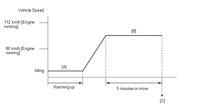
CONFIRMATION DRIVING PATTERN

HINT:

  • After repair has been completed, clear the DTC and then check that the vehicle has returned to normal by performing the following All Readiness check procedure.

    Click here

  • When clearing the permanent DTCs, refer to the "CLEAR PERMANENT DTC" procedure.

    Click here

  1. Connect the Techstream to the DLC3.
  2. Turn the power switch on (IG).
  3. Turn the Techstream on.
  4. Clear the DTCs (even if no DTCs are stored, perform the clear DTC procedure).
  5. Turn the power switch off and wait for at least 30 seconds.
  6. Turn the power switch on (IG).
  7. Turn the Techstream on.
  8. Put the engine in Inspection Mode (Maintenance Mode).

    Click here

  9. Start the engine and warm it up until the engine coolant temperature is 70°C (158°F) or higher [A].
  10. With the engine running, drive the vehicle at approximately 80 km/h (50 mph) to 112 km/h (70 mph) for 5 minutes or more [B].

    CAUTION:

    When performing the confirmation driving pattern, obey all speed limits and traffic laws.

    HINT:

    • Drive while keeping the engine load as stable as possible.
    • If the engine stops, further depress the accelerator pedal to restart the engine.
  11. Enter the following menus: Powertrain / Engine / Trouble Codes [C].
  12. Read the pending DTCs.

    HINT:

    • If a pending DTC is output, the system is malfunctioning.
    • If a pending DTC is not output, perform the following procedure.
  13. Enter the following menus: Powertrain / Engine / Utility / All Readiness.
  14. Input the DTC: P010064.
  15. Check the DTC judgment result.

    Techstream Display

    Description

    NORMAL

    • DTC judgment completed
    • System normal

    ABNORMAL

    • DTC judgment completed
    • System abnormal

    INCOMPLETE

    • DTC judgment not completed
    • Perform driving pattern after confirming DTC enabling conditions

    HINT:

    • If the judgment result is NORMAL, the system is normal.
    • If the judgment result is ABNORMAL, the system is malfunctioning.
    • If the judgment result is INCOMPLETE, perform steps [B] through [C] again.
    • [A] to [C]: Normal judgment procedure.

      The normal judgment procedure is used to complete DTC judgment and also used when clearing permanent DTCs.

    • When clearing the permanent DTCs, do not disconnect the cable from the auxiliary battery terminal or attempt to clear the DTCs during this procedure, as doing so will clear the universal trip and normal judgment histories.

WIRING DIAGRAM

Refer to DTC P010012.

Click here

CAUTION / NOTICE / HINT

NOTICE:

  • Vehicle Control History may be stored in the hybrid vehicle control ECU assembly if the engine is malfunctioning. Certain vehicle condition information is recorded when Vehicle Control History is stored. Reading the vehicle conditions recorded in both the Freeze Frame Data and Vehicle Control History can be useful for troubleshooting.

    Click here

    (Select Powertrain in Health Check and then check the time stamp data.)

    Click here

  • If any "Engine Malfunction" Vehicle Control History item has been stored in the hybrid vehicle control ECU assembly, make sure to clear it. However, as all Vehicle Control History items are cleared simultaneously, if any Vehicle Control History items other than "Engine Malfunction" are stored, make sure to perform any troubleshooting for them before clearing Vehicle Control History.

    Click here

HINT:

Read Freeze Frame Data using the Techstream. The ECM records vehicle and driving condition information as Freeze Frame Data the moment a DTC is stored. When troubleshooting, Freeze Frame Data can help determine if the vehicle was moving or stationary, if the engine was warmed up or not, if the air fuel ratio was lean or rich, and other data from the time the malfunction occurred.

PROCEDURE

1.

CHECK ANY OTHER DTCS OUTPUT (IN ADDITION TO DTC P010064)

(a) Connect the Techstream to the DLC3.

(b) Turn the power switch on (IG).

(c) Turn the Techstream on.

(d) Enter the following menus: Powertrain / Engine / Trouble Codes.

(e) Read the DTCs.

Powertrain > Engine > Trouble Codes

Result

Proceed to

DTC P010064 is output

A

DTC P010064 and other DTCs are output

B

HINT:

If any DTCs other than P010064 are output, troubleshoot those DTCs first.

B

GO TO DTC CHART

A

2.

CHECK INTAKE SYSTEM

(a) Check the intake system for vacuum leaks.

Click here

OK:

No leaks from intake system.

HINT:

Perform "Inspection After Repair" after repairing or replacing the intake system.

Click here

NG

REPAIR OR REPLACE INTAKE SYSTEM

OK

3.

CHECK PCV VALVE AND HOSE CONNECTIONS

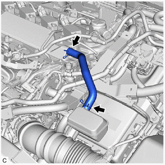
(a) Check the PCV hose connections.

(b) Check the PCV valve.

Click here

OK:

PCV hose and PCV valve are connected correctly and are not damaged.

NG

REPAIR OR REPLACE PCV VALVE OR HOSE

OK

4.

PERFORM ACTIVE TEST USING TECHSTREAM (CONTROL THE EGR STEP POSITION)

(a) Connect the Techstream to the DLC3.

(b) Turn the power switch on (IG).

(c) Turn the Techstream on.

(d) Put the engine in Inspection Mode (Maintenance Mode).

Powertrain > Hybrid Control > Utility

Tester Display

Inspection Mode

(e) Start the engine and warm it up until the engine coolant temperature reaches 75°C (167°F) or higher.

HINT:

The A/C switch and all accessories should be off.

(f) Enter the following menus: Powertrain / Engine / Active Test / Control the EGR Step Position / Data List / Intake Manifold Absolute Pressure, Coolant Temperature and Engine Independent.

Powertrain > Engine > Active Test

Active Test Display

Control the EGR Step Position

Data List Display

Intake Manifold Absolute Pressure

Coolant Temperature

Engine Independent

(g) Confirm that the value of Data List item Engine Independent is "Operate" then check the value of Intake Manifold Absolute Pressure while performing the Active Test.

NOTICE:

  • Do not leave the EGR valve open for 10 seconds or more during the Active Test.
  • Be sure to return the EGR valve to step 0 when the Active Test is completed.
  • Do not open the EGR valve 30 steps or more during the Active Test.

OK:

The value of Intake Manifold Absolute Pressure changes in response to the EGR step position when the value of Engine Independent is "Operate".

Standard:

-

Control the EGR Step Position (Active Test)

0 Steps

0 to 30 Steps

Intake Manifold Absolute Pressure

(Data List)

(EGR valve is fully closed)

Intake Manifold Absolute Pressure value is at least +10 kPa (1.45 psi) higher than when EGR valve is fully closed

HINT:

  • If the value of Data List item Engine Independent is "Not Opr" when the engine is idling, charge control is being performed. Perform the Active Test after charge control is complete ("Operate" is displayed).
  • While performing the Active Test, if the increase in the value of Intake Manifold Absolute Pressure is small, the EGR valve assembly may be malfunctioning.
  • Even if the EGR valve assembly is malfunctioning, rough idling or an increase in the value of Intake Manifold Absolute Pressure may occur while performing the Active Test. However, the amount that the value of Intake Manifold Absolute Pressure increases will be smaller than normal.
OK

GO TO STEP 6

NG

5.

INSPECT EGR VALVE ASSEMBLY

(a) Remove the EGR valve assembly.

Click here

(b) Check if the EGR valve is stuck open.

OK:

EGR valve is tightly closed.

HINT:

Perform "Inspection After Repair" after replacing the EGR valve assembly.

Click here

NG

REPLACE EGR VALVE ASSEMBLY

OK

6.

REPLACE MASS AIR FLOW METER SUB-ASSEMBLY

(a) Replace the mass air flow meter sub-assembly.

Click here

HINT:

Perform "Inspection After Repair" after replacing the mass air flow meter sub-assembly.

Click here

NEXT

7.

CLEAR DTC

(a) Connect the Techstream to the DLC3.

(b) Turn the power switch on (IG).

(c) Turn the Techstream on.

(d) Clear the DTCs.

Powertrain > Engine > Clear DTCs

(e) Turn the power switch off and wait for at least 30 seconds.

NEXT

8.

CONFIRM WHETHER MALFUNCTION HAS BEEN SUCCESSFULLY REPAIRED

(a) Drive the vehicle in accordance with the driving pattern described in Confirmation Driving Pattern.

(b) Enter the following menus: Powertrain / Engine / Utility / All Readiness.

Powertrain > Engine > Utility

Tester Display

All Readiness

(c) Input the DTC: P010064.

(d) Check the DTC judgment result.

Techstream Display

Description

NORMAL

  • DTC judgment completed
  • System normal

ABNORMAL

  • DTC judgment completed
  • System abnormal

INCOMPLETE

  • DTC judgment not completed
  • Perform driving pattern after confirming DTC enabling conditions
NEXT

END

    Mass or Volume Air Flow Sensor "A" Circuit Short to Battery (P010012,P010014)

    Manifold Absolute Pressure / Barometric Pressure Sensor Circuit Short to Ground (P010511)

    See More:

    Toyota Avalon (XX50) 2019-2022 Service & Repair Manual > Occupant Classification System(for Gasoline Model): How To Proceed With Troubleshooting
    CAUTION / NOTICE / HINT HINT: Use the following procedure to troubleshoot the occupant classification system. *: Use the Techstream. PROCEDURE 1. VEHICLE BROUGHT TO WORKSHOP NEXT 2. CUSTOMER PROBLEM ANALYSIS (a) Confirm problem symptoms. Click here NEXT 3. CHECK CAN COMMUNICATION SYSTEM* (a) Using t ...

    Toyota Avalon (XX50) 2019-2022 Owners Manual

    Toyota Avalon (XX50) 2019-2022 Service & Repair Manual

    © 2024 Copyright www.tavalon.net
    0.0196