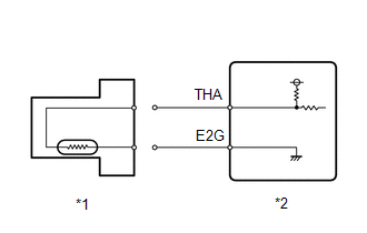
DESCRIPTION 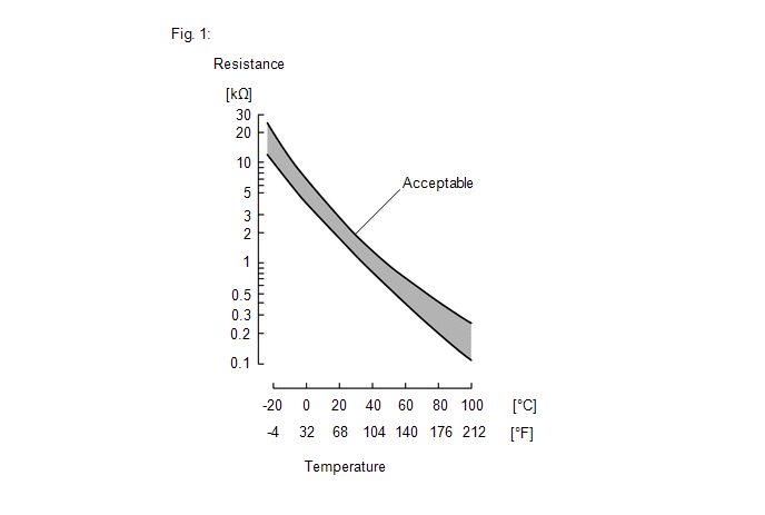 The intake air temperature sensor, mounted on the mass air flow meter sub-assembly, monitors the intake air temperature. The intake air temperature sensor is a built-in thermistor with a resistance that varies according to the temperature of the intake air. When the intake air temperature is low, the resistance of the thermistor increases. When the temperature is high, the resistance drops. These variations in resistance are transmitted to the ECM as voltage changes (see Fig. 1). The intake air temperature sensor is powered by a 5 V supply from the THA terminal of the ECM, via resistor R. Resistor R and the intake air temperature sensor are connected in series. When the resistance value of the intake air temperature sensor changes, according to changes in the intake air temperature, the voltage at terminal THA also varies. Based on this signal, the ECM performs various checks andcompensations related to intake air temperature in the engine management system. HINT: When DTC P011011 is stored, the ECM enters fail-safe mode. During fail-safe mode, the intake air temperature is estimated to be 20°C (68°F) by the ECM. Fail-safe mode continues until a pass condition is detected, and the power switch is then turned off.
HINT: When this DTC is output, check the intake air temperature in the Data List. Enter the following menus: Powertrain / Engine / Data List / Intake Air Temperature.
If the Data List value is normal it may be due to a temporary recovery from the malfunction condition. Check for intermittent problems. Click here
MONITOR DESCRIPTION The ECM monitors the sensor voltage and uses this value to calculate the intake air temperature. When the sensor output voltage deviates from the normal operating range, the ECM interprets this as a malfunction in the intake air temperature sensor (mass air flow meter sub-assembly) circuit, illuminate the MIL and stores a DTC. Example: If the intake air temperature sensor output voltage is less than 0.176 V for 0.5 seconds or more, the ECM will illuminate the MIL and store this DTC. MONITOR STRATEGY
TYPICAL ENABLING CONDITIONS
TYPICAL MALFUNCTION THRESHOLDS
CONFIRMATION DRIVING PATTERN HINT:
WIRING DIAGRAM Refer to DTC P010012. Click here
CAUTION / NOTICE / HINT NOTICE:
HINT: Read Freeze Frame Data using the Techstream. The ECM records vehicle and driving condition information as Freeze Frame Data the moment a DTC is stored. When troubleshooting, Freeze Frame Data can help determine if the vehicle was moving or stationary, if the engine was warmed up or not, if the air fuel ratio was lean or rich, and other data from the time the malfunction occurred. PROCEDURE
(a) Disconnect the mass air flow meter sub-assembly connector. (b) Connect the Techstream to the DLC3. (c) Turn the power switch on (IG). (d) Turn the Techstream on. (e) Enter the following menus: Powertrain / Engine / Data List / Intake Air Temperature. Powertrain > Engine > Data List
(f) According to the display on the Techstream, read the Data List. OK:
HINT: Perform "Inspection After Repair" after replacing the mass air flow meter sub-assembly. Click here
(a) Disconnect the mass air flow meter sub-assembly connector. (b) Disconnect the ECM connector. (c) Measure the resistance according to the value(s) in the table below. Standard Resistance:
|
Toyota Avalon (XX50) 2019-2022 Service & Repair Manual > Can Communication System(for Gasoline Model): Parking Assist ECU Communication Stop Mode
DESCRIPTION Detection Item Symptom Trouble Area Parking Assist ECU Communication Stop Mode Any of the following conditions are met: Communication stop for "Panoramic View Monitor / Circumference Monitoring Camera Control Module" is indicated on the "Communication Bus Check" screen of the Techstream. ...


