DESCRIPTION The throttle position sensor is built into the throttle body with motor assembly and detects the opening angle of the throttle valve. This sensor is a non-contact type sensor. It uses Hall-effect elements in order to yield accurate signals even in extreme driving conditions, such as at high speeds as well as very low speeds. The throttle position sensor is built into the throttle body assembly and detects the opening angle of the throttle valve. This sensor is a non-contact type sensor. It uses Hall-effect elements in order to yield accurate signals even in extreme driving conditions, such as at high speeds as well as very low speeds. As the valve closes, the sensor output voltage decreases and as the valve opens, the sensor output voltage increases. The ECM calculates the throttle valve opening angle according to these signals and controls the throttle actuator in response to a request from the hybrid system. These signals are also used in calculations such as air fuel ratio correction, power increase correction and fuel-cut control. 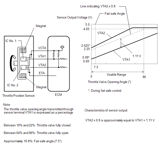
HINT:
MONITOR DESCRIPTION The ECM uses the throttle position sensor to monitor the throttle valve opening angle. If the VTA1 terminal voltage is less than the threshold, the ECM will illuminate the MIL and store this DTC. MONITOR STRATEGY
TYPICAL ENABLING CONDITIONS
TYPICAL MALFUNCTION THRESHOLDS
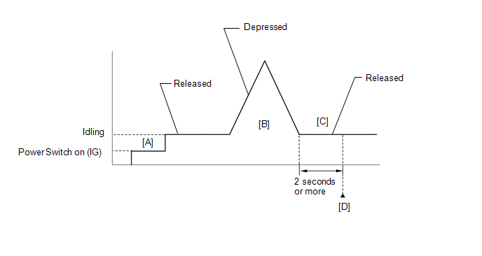
CONFIRMATION DRIVING PATTERN HINT:
FAIL-SAFE When this DTC is stored, the ECM enters fail-safe mode. During fail-safe mode, the ECM cuts the current to the throttle actuator, and the throttle valve is returned to a 7.5° throttle valve opening angle by the return spring. The ECM then adjusts the engine output, by controlling the fuel injection (intermittent fuel cut) and ignition timing, in accordance with the engine torque request signal sent from the hybrid vehicle control ECU, to allow the vehicle to continue being driven at a minimal speed. If the accelerator pedal is depressed firmly and gently, the vehicle can be driven slowly. Fail-safe mode continues until a pass condition is detected, and the power switch is turned off. WIRING DIAGRAM 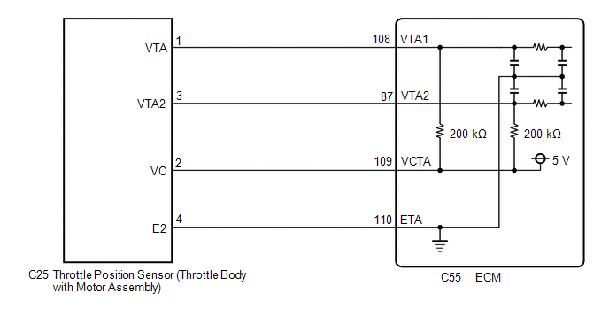 CAUTION / NOTICE / HINT NOTICE:
HINT: Read Freeze Frame Data using the Techstream. The ECM records vehicle and driving condition information as Freeze Frame Data the moment a DTC is stored. When troubleshooting, Freeze Frame Data can help determine if the vehicle was moving or stationary, if the engine was warmed up or not, if the air fuel ratio was lean or rich, and other data from the time the malfunction occurred. PROCEDURE
(a) Connect the Techstream to the DLC3. (b) Turn the power switch on (IG). (c) Turn the Techstream on. (d) Enter the following menus: Powertrain / Engine / Data List / Throttle Position Sensor No.1 Voltage. Powertrain > Engine > Data List
(e) Read the values displayed on the Techstream. (f) Disconnect the throttle body with motor assembly connector. (g) Compare the value of the Data List item Throttle Position Sensor No.1 Voltage after disconnecting the throttle body with motor assembly connector to the value when the connector was connected.
HINT: Perform "Inspection After Repair" after replacing the throttle body with motor assembly. Click here
(a) Disconnect the throttle body with motor assembly connector. (b) Disconnect the ECM connector. (c) Measure the resistance according to the value(s) in the table below. Standard Resistance:
| |||||||||||||||||||||||||||||||||||||||||||||||||||||||||||||||||||||||||||||||||||||||||||
Toyota Avalon (XX50) 2019-2022 Service & Repair Manual > Occupant Classification System(for Hv Model): Diagnostic Trouble Code Chart
DIAGNOSTIC TROUBLE CODE CHART Occupant Classification System DTC No. Detection Item Link B1771 Passenger Side Buckle Switch Circuit Malfunction B1780 Front Occupant Classification Sensor LH Circuit Malfunction B1782 Rear Occupant Classification Sensor LH Circuit Malfunction B1785 Front Occupant Clas ...


