DESCRIPTION A flat-type knock control sensor (non-resonant type) has a structure that can detect vibrations between approximately 5 and 15 kHz. The knock control sensor is fitted onto the engine block to detect engine knocking. The knock control sensor contains a piezoelectric element which generates a voltage when it becomes deformed. The voltage is generated when the engine block vibrates due to knocking. Any occurrence of engine knocking can be suppressed by delaying the ignition timing. HINT: When DTC P032511 is stored, the ECM enters fail-safe mode. During fail-safe mode, the ignition timing is delayed to its maximum retardation. Fail-safe mode continues until the power switch is turned off.
Reference: Inspection using an oscilloscope 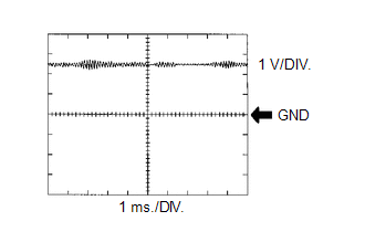 HINT: The correct waveform is as shown.
MONITOR DESCRIPTION If the output voltage transmitted by the knock control sensor remains low for 1 second or more, the ECM interprets this as a malfunction in the sensor circuit, illuminates the MIL and stores this DTC. MONITOR STRATEGY
TYPICAL ENABLING CONDITIONS
TYPICAL MALFUNCTION THRESHOLDS
CONFIRMATION DRIVING PATTERN HINT:
WIRING DIAGRAM 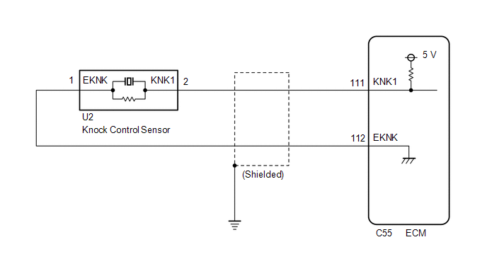 CAUTION / NOTICE / HINT NOTICE:
HINT: Read Freeze Frame Data using the Techstream. The ECM records vehicle and driving condition information as Freeze Frame Data the moment a DTC is stored. When troubleshooting, Freeze Frame Data can help determine if the vehicle was moving or stationary, if the engine was warmed up or not, if the air fuel ratio was lean or rich, and other data from the time the malfunction occurred. PROCEDURE
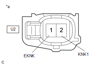
(a) Disconnect the knock control sensor connector. (b) Turn the power switch on (IG). (c) Measure the voltage according to the value(s) in the table below. Standard Voltage:
(a) Inspect the knock control sensor. Click here HINT: Perform "Inspection After Repair" after replacing the knock control sensor. Click here
(a) Disconnect the knock control sensor connector. (b) Disconnect the ECM connector. (c) Measure the resistance according to the value(s) in the table below. Standard Resistance:
(a) Connect the Techstream to the DLC3. (b) Turn the power switch on (IG). (c) Turn the Techstream on. (d) Clear the DTCs. Powertrain > Engine > Clear DTCs(e) Turn the power switch off and wait for at least 30 seconds.
(a) Drive the vehicle in accordance with the driving pattern described in Confirmation Driving Pattern. (b) Enter the following menus: Powertrain / Engine / Trouble Codes. (c) Read the DTCs. Powertrain > Engine > Trouble Codes
|
Toyota Avalon (XX50) 2019-2022 Service & Repair Manual > Luggage Compartment Door Opener System(for Gasoline Model): Parts Location
PARTS LOCATION ILLUSTRATION *1 LUGGAGE COMPARTMENT DOOR OPENING SWITCH ASSEMBLY *2 DLC3 *3 MAIN BODY ECU (MULTIPLEX NETWORK BODY ECU) *4 INSTRUMENT PANEL JUNCTION BLOCK ASSEMBLY - DOOR BACK RELAY - TRUNK OPN FUSE *5 CERTIFICATION ECU (SMART KEY ECU ASSEMBLY) - - ILLUSTRATION *1 LUGGAGE COMPARTMENT D ...


