DESCRIPTION Refer to DTC P059712. Click here
 |
DTC No. | Detection Item |
DTC Detection Condition | Trouble Area |
MIL | Memory |
Note | | P059714 |
Thermostat Heater Control Circuit Short to Ground or Open |
Open or short in thermostat heater circuit and power supply circuit
(1 trip detection logic). |
- Open or short in thermostat heater circuit
- Thermostat heater (water inlet with thermostat sub-assembly)
- ECM
| Comes on |
DTC stored | SAE Code: P0598 | Related Data List |
DTC No. | Data List | |
P059714 | Coolant Temperature | MONITOR DESCRIPTION
The ECM monitors the output voltage while the thermostat heater is operating.
The thermostat heater turns on and off according to ON/OFF switching of a transistor inside the ECM.
If
a continuous mismatch occurs between the ECM transistor state and the
output voltage, the ECM determines there is a malfunction in the
thermostat heater circuit and stores a DTC. MONITOR STRATEGY |
Related DTCs | P0598: Thermostat heater range check (low voltage) | |
Required Sensors/Components (Main) | Thermostat heater | |
Required Sensors/Components (Related) | - | |
Frequency of Operation | Continuous | |
Duration | 3 seconds | | MIL Operation |
Immediate | | Sequence of Operation |
None | TYPICAL ENABLING CONDITIONS |
Monitor runs whenever the following DTCs are not stored |
None | | All of the following conditions are met |
- | | Either of the following conditions is met |
1 or 2 | | 1. Both of the following conditions are met |
(a) and (b) | | (a) Last thermostat heater output terminal voltage level |
Low | | (b) Current thermostat heater output terminal voltage level |
Low | | 2. Both of the following conditions are met |
(c) and (d) | |
(c) Last thermostat heater output terminal voltage level |
High | | (d) Current thermostat heater output terminal voltage level |
High | | Auxiliary battery voltage |
8 V or higher | |
Command to thermostat heater |
Off | TYPICAL MALFUNCTION THRESHOLDS |
Thermostat heater output terminal voltage level |
Low | CONFIRMATION DRIVING PATTERN
HINT:
- After repair has been completed, clear the DTC and then check that the
vehicle has returned to normal by performing the following All Readiness
check procedure.
Click here
- When clearing the permanent DTCs, refer to the "CLEAR PERMANENT DTC" procedure.
Click here
- Connect the Techstream to the DLC3.
- Turn the power switch on (IG).
- Turn the Techstream on.
- Clear the DTCs (even if no DTCs are stored, perform the clear DTC procedure).
- Turn the power switch off and wait for at least 30 seconds.
- Turn the power switch on (IG).
- Turn the Techstream on.
- Put the engine in Inspection Mode (Maintenance Mode).
Click here
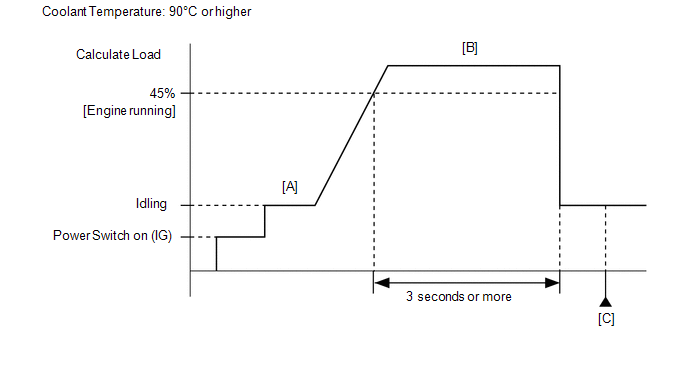
- Start the engine and warm it up until the engine coolant temperature reaches 75°C (167°F) or higher [A].
- Enter the following menus: Powertrain / Engine / Data List / Calculate Load and Coolant Temperature.
- With the engine running, drive the vehicle for at least 3 seconds at the
Calculate Load of 45% or more and the Coolant Temperature of 90°C
(194°F) or higher [B].
CAUTION:
When performing the confirmation driving pattern, obey all speed limits and traffic laws.
HINT:
If the engine stops, further depress the accelerator pedal to restart the engine.
- Stop the vehicle.
- Enter the following menus: Powertrain / Engine / Trouble Codes [C].
- Read the pending DTCs.
HINT:
- If a pending DTC is output, the system is malfunctioning.
- If a pending DTC is not output, perform the following procedure.
- Enter the following menus: Powertrain / Engine / Utility / All Readiness.
- Input the DTC: P059714.
- Check the DTC judgment result.
|
Techstream Display |
Description |
|
NORMAL |
- DTC judgment completed
- System normal
|
|
ABNORMAL |
- DTC judgment completed
- System abnormal
|
|
INCOMPLETE |
- DTC judgment not completed
- Perform driving pattern after confirming DTC enabling conditions
|
HINT:
WIRING DIAGRAM Refer to DTC P059712. Click here
CAUTION / NOTICE / HINT
NOTICE:
HINT: Read
Freeze Frame Data using the Techstream. The ECM records vehicle and
driving condition information as Freeze Frame Data the moment a DTC is
stored. When troubleshooting, Freeze Frame Data can help determine if
the vehicle was moving or stationary, if the engine was warmed up or
not, if the air fuel ratio was lean or rich, and other data from the
time the malfunction occurred. PROCEDURE
| 1. |
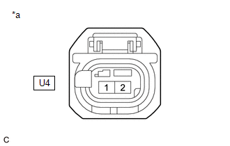
CHECK TERMINAL VOLTAGE (POWER SOURCE OF THERMOSTAT HEATER (WATER INLET WITH THERMOSTAT SUB-ASSEMBLY)) |
|
*a | Front view of wire harness connector
(to Thermostat Heater (Water Inlet with Thermostat Sub-assembly)) |
(a) Disconnect the thermostat heater (water inlet with thermostat sub-assembly) connector.
(b) Turn the power switch on (IG). (c) Measure the voltage according to the value(s) in the table below.
Standard Voltage: |
Tester Connection | Condition |
Specified Condition | |
U4-1 - Body ground | Power switch on (IG) |
11 to 14 V |
| NG |
 | GO TO STEP 4 |
|
OK |
 | |
| 2. |
INSPECT THERMOSTAT HEATER (WATER INLET WITH THERMOSTAT SUB-ASSEMBLY) |
(a) Inspect the thermostat heater (water inlet with thermostat sub-assembly).
Click here
| NG |
| REPLACE THERMOSTAT HEATER (WATER INLET WITH THERMOSTAT SUB-ASSEMBLY) |
|
OK | |
| |
| 3. |
CHECK HARNESS AND CONNECTOR (THERMOSTAT HEATER (WATER INLET WITH THERMOSTAT SUB-ASSEMBLY) - ECM) |
(a) Disconnect the thermostat heater (water inlet with thermostat sub-assembly) connector.
(b) Disconnect the ECM connector. (c) Measure the resistance according to the value(s) in the table below.
Standard Resistance: |
Tester Connection | Condition |
Specified Condition | |
U4-2 - C55-7 (HTHM) | Always |
Below 1 Ω | |
U4-2 or C55-7 (HTHM) - Body ground and other terminals |
Always | 10 kΩ or higher |
| OK |
| REPLACE ECM |
| NG |
| REPAIR OR REPLACE HARNESS OR CONNECTOR |
| 4. |
INSPECT EFI-MAIN NO. 2 RELAY | (a) Inspect the EFI-MAIN NO. 2 relay.
Click here
| NG |
| REPLACE EFI-MAIN NO. 2 RELAY |
|
OK | |
| |
| 5. |
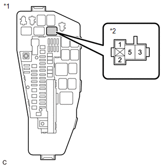
CHECK TERMINAL VOLTAGE (POWER SOURCE OF EFI-MAIN NO. 2 RELAY) |
|
*1 | No. 1 Engine Room Relay Block and No. 1 Junction Block Assembly | |
*2 | EFI-MAIN NO. 2 Relay |
(a) Remove the EFI-MAIN NO. 2 relay from the No. 1 engine room relay block and No. 1 junction block assembly.
(b) Measure the voltage according to the value(s) in the table below. Standard Voltage: |
Tester Connection | Condition |
Specified Condition | |
3 (EFI-MAIN NO. 2 relay) - Body ground |
Always | 11 to 14 V |
| NG |
| REPAIR OR REPLACE HARNESS OR CONNECTOR (AUXILIARY BATTERY - EFI-MAIN NO. 2 RELAY) |
|
OK | |
| |
| 6. |
CHECK HARNESS AND CONNECTOR (EFI-MAIN NO. 2 RELAY - BODY GROUND) |
(a) Remove the EFI-MAIN NO. 2 relay from the No. 1 engine room relay block and No. 1 junction block assembly.
(b) Measure the resistance according to the value(s) in the table below.
Standard Resistance: |
Tester Connection | Condition |
Specified Condition | |
1 (EFI-MAIN NO. 2 relay) - Body ground |
Always | Below 1 Ω |
| NG |
| REPAIR OR REPLACE HARNESS OR CONNECTOR |
|
OK | |
| |
| 7. |
CHECK HARNESS AND CONNECTOR (EFI-MAIN NO. 2 RELAY - THERMOSTAT HEATER (WATER INLET WITH THERMOSTAT SUB-ASSEMBLY)) |
(a) Remove the EFI-MAIN NO. 2 relay from the No. 1 engine room relay block and No. 1 junction block assembly.
(b) Disconnect the thermostat heater (water inlet with thermostat sub-assembly) connector.
(c) Measure the resistance according to the value(s) in the table below.
Standard Resistance: |
Tester Connection | Condition |
Specified Condition | |
5 (EFI-MAIN NO. 2 relay) - U4-1 |
Always | Below 1 Ω | |
5 (EFI-MAIN NO. 2 relay) or U4-1 - Body ground and other terminals |
Always | 10 kΩ or higher |
| OK |
| REPAIR OR REPLACE HARNESS OR CONNECTOR (EFI-MAIN NO. 1 RELAY - EFI-MAIN NO. 2 RELAY) |
| NG |
| REPAIR OR REPLACE HARNESS OR CONNECTOR | | 

