Components COMPONENTS ILLUSTRATION 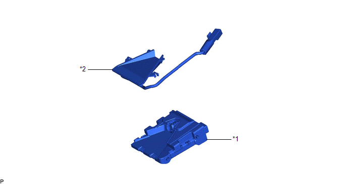
Installation INSTALLATION PROCEDURE 1. INSTALL FORWARD RECOGNITION WITH HEATER HOOD SUB-ASSEMBLY NOTICE:
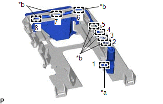
(a) Engage the 2 guides and 2 claws as indicated by the arrows, in the order shown in the illustration. 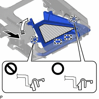
NOTICE: Make sure that the 2 claws are engaged as shown in the illustration. Failure to do so may result in the malfunction of systems that use the forward recognition camera.
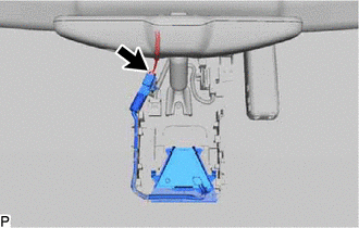
(c) Connect the connector. 2. INSTALL FORWARD RECOGNITION CAMERA Click here Removal REMOVAL PROCEDURE 1. REMOVE FORWARD RECOGNITION CAMERA Click here
2. REMOVE FORWARD RECOGNITION WITH HEATER HOOD SUB-ASSEMBLY
(c) Pull the forward recognition hood in the direction indicated by the arrow (1) shown in the illustration to disengage the 2 claws. 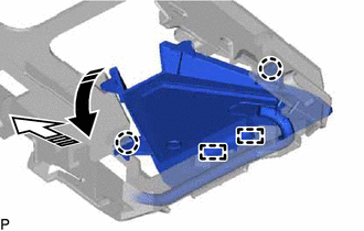
(d) Pull the forward recognition hood in the direction indicated by the arrow (2) shown in the illustration to disengage the 2 guides and remove the forward recognition with heater hood sub-assembly. |
Toyota Avalon (XX50) 2019-2022 Service & Repair Manual > Can Communication System(for Gasoline Model): Terminals Of Ecu
TERMINALS OF ECU NOTICE: After turning the engine switch off, waiting time may be required before disconnecting the cable from the negative (-) battery terminal. Therefore, make sure to read the disconnecting the cable from the negative (-) battery terminal notices before proceeding with work. Click ...