DESCRIPTION The driving support ECU assembly receives a lane departure alert switch signal from the steering pad switch assembly and sends the signal to the forward recognition camera via CAN communication. WIRING DIAGRAM 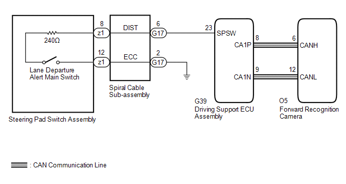 CAUTION / NOTICE / HINT NOTICE: The vehicle is equipped with a Supplemental Restraint System (SRS) which includes components such as airbags. Before servicing (including removal or installation of parts), be sure to read the precaution for Supplemental Restraint System. Click here PROCEDURE
(a) Connect the Techstream to the DLC3. (b) Turn the engine switch on (IG). (c) Turn the Techstream on. (d) Enter the following menus: System Select / Can Bus Check. Click here
(a) Connect the Techstream to the DLC3. (b) Turn the engine switch on (IG). (c) Turn the Techstream on. (d) Enter the following menus: System Select / Health Check. (e) Check DTCs. (f) Turn the engine switch off.
(a) Remove the steering pad switch assembly. Click here (b) Inspect the steering pad switch assembly. Click here
(a) Remove the spiral cable sub-assembly. Click here (b) Inspect the spiral cable sub-assembly. Click here
(a) Disconnect the G17 spiral cable sub-assembly connector. (b) Disconnect the G39 driving support ECU assembly connector. (c) Measure the resistance according to the value(s) in the table below. Standard Resistance (Check for Open):
Standard Resistance (Check for Short):
(d) Connect the G39 driving support ECU assembly connector. (e) Connect the G17 spiral cable sub-assembly connector.
|
Toyota Avalon (XX50) 2019-2022 Service & Repair Manual > Hybrid Control System: Hybrid/EV Battery Air Temperature Sensor "A" Circuit Short to Ground (P0AAC11,P0AAC15)
DESCRIPTION The inlet air temperature sensor (battery) is mounted on the HV battery. The resistance of the sensor varies in accordance with changes in the intake air temperature. The characteristics of the inlet air temperature sensor are the same as those of the battery temperature sensors (Click h ...


