|
DTC No. | Detection Item |
Order of Priority |
Inspection Pattern |
|
1 | 2 |
3 | 4 |
5 |
| Microcomputer Malfunction |
Power Source Circuit Malfunction |
Communication System Malfunction |
Sensor and Actuator Circuit Malfunction |
System Malfunction |
|
P056014 | System Voltage (BATT) Circuit Short to Ground or Open |
- | ○ |
- | - |
- | - |
|
P060647 | Hybrid/EV Powertrain Control Module Processor Watchdog / Safety MCU Failure |
○ | - |
- | - |
- | - |
|
P060687 | Hybrid/EV Powertrain Control Module Processor to Monitoring Processor Missing Message |
○ | - |
- | - |
- | - |
|
P060694 | Hybrid/EV Powertrain Control Module Processor Unexpected Operation |
○ | - |
- | - |
- | - |
|
P060A29 | Hybrid/EV Powertrain Control Module Monitoring Processor Signal Invalid |
○ | - |
- | - |
- | - |
|
P060A44 | Hybrid/EV Powertrain Control Module Monitoring Processor Data Memory Failure |
○ | - |
- | - |
- | - |
|
P060A45 | Hybrid/EV Powertrain Control Module Monitoring Processor Program Memory Failure |
○ | - |
- | - |
- | - |
|
P060A47 | Hybrid/EV Powertrain Control Module Monitoring Processor Watchdog / Safety MCU Failure |
○ | - |
- | - |
- | - |
|
P060A49 | Hybrid/EV Powertrain Control Module Monitoring Processor Internal Electronic Failure |
○ | - |
- | - |
- | - |
|
P060A87 | Hybrid/EV Powertrain Control Module Processor from Monitoring Processor Missing Message |
○ | - |
- | - |
- | - |
|
P060A94 | Hybrid/EV Powertrain Control Module Monitoring Processor Unexpected Operation |
○ | - |
- | - |
- | - |
|
P060B1C | Hybrid/EV Powertrain Control Module A/D Processing Voltage Out of Range |
○ | - |
- | - |
- | - |
|
P060B49 | Hybrid/EV Powertrain Control Module A/D Processing Internal Electronic Failure |
○ | - |
- | - |
- | - |
|
P060B71 | Hybrid/EV Powertrain Control Module A/D Processing Actuator Stuck |
○ | - |
- | - |
- | - |
|
P062F44 | Hybrid/EV Powertrain Control Module EEPROM Data Memory Failure |
○ | - |
- | - |
- | - |
|
P062F46 | Hybrid/EV Powertrain Control Module EEPROM Calibration / Parameter Memory Failure |
○ | - |
- | - |
- | - |
|
P06881F | ECM/PCM Power Relay Sense Circuit Intermittent |
- | ○ |
- | - |
- | - |
|
P070562 | Transmission Range Sensor "A" Circuit (PRNDL Input) Signal Compare Failure |
- | - |
- | ○ |
- | - |
|
P0A0A13 | High Voltage System Interlock Circuit Open |
- | - |
- | - |
○ | - |
|
P0A0A92 | High Voltage System Interlock Performance or Incorrect Operation |
- | - |
- | - |
○ | - |
|
P0A1B49 | Drive Motor "A" Control Module Internal Electronic Failure |
○ | - |
- | - |
- | - |
|
P0A1B94 | Drive Motor "A" Control Module Unexpected Operation |
○ | - |
- | - |
- | - |
|
P0A2A11 | Drive Motor "A" Temperature Sensor Circuit Short to Ground |
- | - |
- | ○ |
- | - |
|
P0A2A15 | Drive Motor "A" Temperature Sensor Circuit Short to Auxiliary Battery or Open |
- | - |
- | ○ |
- | - |
|
P0A2A1C | Drive Motor "A" Temperature Sensor Voltage Out of Range |
- | - |
- | ○ |
- | - |
|
P0A2A1F | Drive Motor "A" Temperature Sensor Circuit Intermittent |
- | - |
- | ○ |
- | - |
|
P0A3611 | Generator Temperature Sensor Circuit Short to Ground |
- | - |
- | ○ |
- | - |
|
P0A3615 | Generator Temperature Sensor Circuit Short to Auxiliary Battery or Open |
- | - |
- | ○ |
- | - |
|
P0A361C | Generator Temperature Sensor Voltage Out of Range |
- | - |
- | ○ |
- | - |
|
P0A361F | Generator Temperature Sensor Circuit Intermittent |
- | - |
- | ○ |
- | - |
|
P0A8100 | Hybrid/EV Battery Cooling Fan 1 Control Circuit High |
- | - |
- | ○ |
- | - |
|
P0A8111 | Hybrid/EV Battery Cooling Fan 1 Circuit Short to Ground |
- | - |
- | ○ |
- | - |
|
P0A8115 | Hybrid/EV Battery Cooling Fan 1 Circuit Short to Auxiliary Battery or Open |
- | - |
- | ○ |
- | - |
|
P0A814B | Hybrid/EV Battery Cooling Fan 1 Over Temperature |
- | - |
- | ○ |
- | - |
|
P0A8196 | Hybrid/EV Battery Cooling Fan 1 Component Internal Failure |
- | - |
- | ○ |
- | - |
|
P0A8198 | Hybrid/EV Battery Cooling Fan 1 Component or System Over Temperature |
- | - |
- | ○ |
- | - |
|
P0A9300 | Inverter "A" Cooling System Performance |
- | - |
- | - |
○ | B |
|
P0A9563 | High Voltage Fuse Accumulated Load History |
- | - |
- | - |
○ | - |
|
P0A9B11 | Hybrid/EV Battery Temperature Sensor "A" Circuit Short to Ground |
- | - |
- | - |
○ | - |
|
P0A9B15 | Hybrid/EV Battery Temperature Sensor "A" Circuit Short to Auxiliary Battery or Open |
- | - |
- | ○ |
- | - |
|
P0A9B1C | Hybrid/EV Battery Temperature Sensor "A" Voltage Out of Range |
- | - |
- | ○ |
- | - |
|
P0A9B2A | Hybrid/EV Battery Temperature Sensor "A" Signal Stuck In Range |
- | - |
- | ○ |
- | - |
|
P0AA000 | Hybrid/EV Battery Positive Contactor Circuit Stuck Closed |
- | - |
- | - |
○ | - |
|
P0AA073 | Hybrid/EV Battery Positive and Negative Contactor Actuator Stuck Closed |
- | - |
- | - |
○ | - |
|
P0AA373 | Hybrid/EV Battery Negative Contactor Actuator Stuck Closed |
- | - |
- | - |
○ | - |
|
P0AA649 | Hybrid/EV Battery Voltage System Isolation Internal Electronic Failure |
- | - |
- | - |
○ | - |
|
P0AA749 | Hybrid/EV Battery Voltage Isolation Sensor Circuit Internal Electronic Failure |
- | - |
- | ○ |
- | - |
|
P0AAC11 | Hybrid/EV Battery Air Temperature Sensor "A" Circuit Short to Ground |
- | - |
- | ○ |
- | - |
|
P0AAC15 | Hybrid/EV Battery Air Temperature Sensor "A" Circuit Short to Auxiliary Battery or Open |
- | - |
- | ○ |
- | - |
|
P0ABF00 | Hybrid/EV Battery Current Sensor "A" Circuit Range/Performance |
- | - |
- | ○ |
- | - |
|
P0ABF11 | Hybrid/EV Battery Current Sensor "A" Circuit Short to Ground |
- | - |
- | ○ |
- | - |
|
P0ABF15 | Hybrid/EV Battery Current Sensor "A" Circuit Short to Auxiliary Battery or Open |
- | - |
- | ○ |
- | - |
|
P0ABF28 | Hybrid/EV Battery Current Sensor "A" Signal Bias Level Out of Range / Zero Adjustment Failure |
- | - |
- | ○ |
- | - |
|
P0ABF2A | Hybrid/EV Battery Current Sensor "A" Signal Stuck In Range |
- | - |
- | ○ |
- | - |
|
P0AC511 | Hybrid/EV Battery Temperature Sensor "B" Circuit Short to Ground |
- | - |
- | ○ |
- | - |
|
P0AC515 | Hybrid/EV Battery Temperature Sensor "B" Circuit Short to Auxiliary Battery or Open |
- | - |
- | ○ |
- | - |
|
P0AC51C | Hybrid/EV Battery Temperature Sensor "B" Voltage Out of Range |
- | - |
- | ○ |
- | - |
|
P0AC52A | Hybrid/EV Battery Temperature Sensor "B" Signal Stuck In Range |
- | - |
- | ○ |
- | - |
|
P0ACA11 | Hybrid/EV Battery Temperature Sensor "C" Circuit Short to Ground |
- | - |
- | ○ |
- | - |
|
P0ACA15 | Hybrid/EV Battery Temperature Sensor "C" Circuit Short to Auxiliary Battery or Open |
- | - |
- | ○ |
- | - |
|
P0ACA1C | Hybrid/EV Battery Temperature Sensor "C" Voltage Out of Range |
- | - |
- | ○ |
- | - |
|
P0ACA2A | Hybrid/EV Battery Temperature Sensor "C" Signal Stuck In Range |
- | - |
- | ○ |
- | - |
|
P0AD911 | Hybrid/EV Battery Positive Contactor Circuit Short to Ground |
- | - |
- | ○ |
- | - |
|
P0AD915 | Hybrid/EV Battery Positive Contactor Circuit Short to Auxiliary Battery or Open |
- | - |
- | ○ |
- | - |
|
P0ADD11 | Hybrid/EV Battery Negative Contactor Circuit Short to Ground |
- | - |
- | ○ |
- | - |
|
P0ADD15 | Hybrid/EV Battery Negative Contactor Circuit Short to Auxiliary Battery or Open |
- | - |
- | ○ |
- | - |
|
P0AE173 | Hybrid/EV Battery Precharge Contactor Actuator Stuck Closed |
- | - |
- | - |
○ | - |
|
P0AE411 | Hybrid/EV Battery Precharge Contactor Circuit Short to Ground |
- | - |
- | ○ |
- | - |
|
P0AE415 | Hybrid/EV Battery Precharge Contactor Circuit Short to Auxiliary Battery or Open |
- | - |
- | ○ |
- | - |
|
P0AFC00 | Hybrid/EV Battery Sensor Module |
○ | - |
- | - |
- | - |
|
P0AFC16 | Hybrid/EV Battery Sensor Module Circuit Voltage Below Threshold |
- | ○ |
- | - |
- | - |
|
P0AFC49 | Hybrid/EV Battery Sensor Module Internal Electronic Failure |
○ | - |
- | - |
- | - |
|
P0AFC62 | Hybrid/EV Battery Sensor Module Signal Compare Failure |
○ | - |
- | - |
- | - |
|
P0AFC96 | Hybrid/EV Battery Sensor Module Component Internal Failure |
○ | - |
- | - |
- | - |
|
P0B231C | Hybrid/EV Battery "A" Voltage Sensor Voltage Out of Range |
- | - |
- | ○ |
- | - |
|
P0B3B14 | Hybrid/EV Battery Voltage Sensor "A" Circuit Short to Ground or Open |
- | - |
- | ○ |
- | - |
|
P0B4014 | Hybrid/EV Battery Voltage Sensor "B" Circuit Short to Ground or Open |
- | - |
- | ○ |
- | - |
|
P0B4514 | Hybrid/EV Battery Voltage Sensor "C" Circuit Short to Ground or Open |
- | - |
- | ○ |
- | - |
|
P0B4A14 | Hybrid/EV Battery Voltage Sensor "D" Circuit Short to Ground or Open |
- | - |
- | ○ |
- | - |
|
P0B4F14 | Hybrid/EV Battery Voltage Sensor "E" Circuit Short to Ground or Open |
- | - |
- | ○ |
- | - |
|
P0B5414 | Hybrid/EV Battery Voltage Sensor "F" Circuit Short to Ground or Open |
- | - |
- | ○ |
- | - |
|
P0B5914 | Hybrid/EV Battery Voltage Sensor "G" Circuit Short to Ground or Open |
- | - |
- | ○ |
- | - |
|
P0B5E14 | Hybrid/EV Battery Voltage Sensor "H" Circuit Short to Ground or Open |
- | - |
- | ○ |
- | - |
|
P0B6314 | Hybrid/EV Battery Voltage Sensor "I" Circuit Short to Ground or Open |
- | - |
- | ○ |
- | - |
|
P0B6814 | Hybrid/EV Battery Voltage Sensor "J" Circuit Short to Ground or Open |
- | - |
- | ○ |
- | - |
|
P0B6D14 | Hybrid/EV Battery Voltage Sensor "K" Circuit Short to Ground or Open |
- | - |
- | ○ |
- | - |
|
P0B7214 | Hybrid/EV Battery Voltage Sensor "L" Circuit Short to Ground or Open |
- | - |
- | ○ |
- | - |
|
P0C3000 | Hybrid/EV Battery State of Charge High |
- | - |
- | - |
○ | - |
|
P0C7396 | Motor Electronics Coolant Pump "A" Component Internal Failure |
- | - |
- | ○ |
- | - |
|
P0C7600 | Hybrid/EV Battery System Discharge Time Too Long |
- | - |
- | - |
○ | - |
|
P0D2D1C | Drive Motor "A" Inverter Voltage Sensor Voltage Out of Range |
- | - |
- | - |
○ | - |
|
P0E311C | Boosting Converter Voltage Sensor "A" Voltage Out of Range |
- | - |
- | - |
○ | - |
|
P160600 | Collision detected or Collision Sensor Connection (Open) |
- | - |
- | - |
- | - |
|
P160604 | Collision detected or Collision Sensor Connection (Open) System Internal Failure |
- | - |
- | - |
- | - |
|
P1A8000 | Hybrid/EV Battery Stack 1 Delta SOC High |
- | - |
- | - |
○ | - |
|
P1AC000 | Hybrid/EV Battery Cell Low Voltage |
- | - |
- | - |
○ | - |
|
P1AD01B | Hybrid/EV Battery Block Circuit Resistance Above Threshold |
- | - |
- | - |
○ | - |
|
P1C2D62 | Hybrid/EV Battery "A" Voltage Sensor/Boosting Converter Voltage Sensor "A" Signal Compare Failure |
- | - |
- | - |
○ | - |
|
P1C6A9F | Motor Shutdown Stuck Off |
- | - |
- | - |
○ | - |
|
P1C6C9F | Generator Shutdown Stuck Off |
- | - |
- | - |
○ | - |
|
P1C7779 | Engine Failed to Start Mechanical Linkage Failure |
- | - |
- | ○ |
- | - |
|
P1C7C49 | Hybrid/EV Battery Voltage System Isolation (A/C Area) Internal Electronic Failure |
- | - |
- | - |
○ | - |
|
P1C7D49 | Hybrid/EV Battery Voltage System Isolation (Hybrid/EV Battery Area) Internal Electronic Failure |
- | - |
- | - |
○ | - |
|
P1C7E49 | Hybrid/EV Battery Voltage System Isolation (Transaxle Area) Internal Electronic Failure |
- | - |
- | - |
○ | - |
|
P1C7F49 | Hybrid/EV Battery Voltage System Isolation (Direct Current Area) Internal Electronic Failure |
- | - |
- | - |
○ | - |
|
P1C8149 | High Voltage Power Resource Circuit Consumption Circuit Short |
- | - |
- | - |
○ | - |
|
P1C8249 | High Voltage Power Resource Circuit Over Loading |
- | - |
- | - |
○ | - |
|
P1C8349 | High Voltage Power Resource Circuit Voltage Sensor after Boosting Malfunction |
- | - |
- | - |
○ | - |
|
P1C8449 | High Voltage Power Resource Circuit Short during Ready ON |
- | - |
- | - |
○ | - |
|
P1C8549 | High Voltage Power Resource Internal Electronic Failure |
- | - |
- | - |
○ | - |
|
P1C8679 | Transmission (Input) Mechanical Linkage Failure |
- | - |
- | - |
○ | - |
|
P1C8779 | Generator Mechanical Linkage Failure |
- | - |
- | - |
○ | - |
|
P1C8879 | Planetary Gear Mechanical Linkage Failure |
- | - |
- | - |
○ | - |
|
P1C9E9F | Hybrid/EV System Reset Stuck Off |
- | - |
- | - |
○ | - |
|
P1C9F11 | Hybrid/EV Battery Current Sensor for Driving Control Circuit Short to Ground |
- | - |
- | ○ |
- | - |
|
P1C9F15 | Hybrid/EV Battery Current Sensor for Driving Control Circuit Short to Auxiliary Battery or Open |
- | - |
- | ○ |
- | - |
|
P1C9F1C | Hybrid/EV Battery Current Sensor for Driving Control Voltage Out of Range |
- | - |
- | ○ |
- | - |
|
P1CBB12 | Hybrid/EV Battery Current Sensor Power Supply Circuit Short to Auxiliary Battery |
- | - |
- | ○ |
- | - |
|
P1CBB14 | Hybrid/EV Battery Current Sensor Power Supply Circuit Short to Ground or Open |
- | - |
- | ○ |
- | - |
|
P1CBE1E | Hybrid/EV Battery Block 1 Voltage Difference Out of Range |
- | - |
- | - |
○ | - |
|
P1CBF1E | Hybrid/EV Battery Block 2 Voltage Difference Out of Range |
- | - |
- | - |
○ | - |
|
P1CC01E | Hybrid/EV Battery Block 3 Voltage Difference Out of Range |
- | - |
- | - |
○ | - |
|
P1CC11E | Hybrid/EV Battery Block 4 Voltage Difference Out of Range |
- | - |
- | - |
○ | - |
|
P1CC21E | Hybrid/EV Battery Block 5 Voltage Difference Out of Range |
- | - |
- | - |
○ | - |
|
P1CC31E | Hybrid/EV Battery Block 6 Voltage Difference Out of Range |
- | - |
- | - |
○ | - |
|
P1CC41E | Hybrid/EV Battery Block 7 Voltage Difference Out of Range |
- | - |
- | - |
○ | - |
|
P1CC51E | Hybrid/EV Battery Block 8 Voltage Difference Out of Range |
- | - |
- | - |
○ | - |
|
P1CC61E | Hybrid/EV Battery Block 9 Voltage Difference Out of Range |
- | - |
- | - |
○ | - |
|
P1CC71E | Hybrid/EV Battery Block 10 Voltage Difference Out of Range |
- | - |
- | - |
○ | - |
|
P1CE213 | PCU Interlock Circuit Open |
- | - |
- | - |
○ | - |
|
P1CE292 | PCU Interlock Performance or Incorrect Operation |
- | - |
- | - |
○ | - |
|
P1CE31C | Hybrid/EV Powertrain Control Module Monitoring Processor A/D Processing Voltage Out of Range |
○ | - |
- | - |
- | - |
|
P1CE349 | Hybrid/EV Powertrain Control Module Monitoring Processor A/D Processing Internal Electronic Failure |
○ | - |
- | - |
- | - |
|
P1CE371 | Hybrid/EV Powertrain Control Module Monitoring Processor A/D Processing Actuator Stuck |
○ | - |
- | - |
- | - |
|
P1CFA12 | IGB Signal Circuit Short to Auxiliary Battery |
○ | - |
- | - |
- | - |
|
P1CFD1E | Hybrid/EV Battery Block 11 Voltage Difference Out of Range |
- | - |
- | - |
○ | - |
|
P212012 | Throttle/Pedal Position Sensor/Switch "D" Circuit Short to Auxiliary Battery |
- | - |
- | ○ |
- | - |
|
P212014 | Throttle/Pedal Position Sensor/Switch "D" Circuit Short to Ground or Open |
- | - |
- | ○ |
- | - |
|
P21201C | Throttle/Pedal Position Sensor/Switch "D" Voltage Out of Range |
- | - |
- | ○ |
- | - |
|
P21201F | Throttle/Pedal Position Sensor/Switch "D" Circuit Intermittent |
- | - |
- | ○ |
- | - |
|
P212512 | Throttle/Pedal Position Sensor/Switch "E" Circuit Short to Auxiliary Battery |
- | - |
- | ○ |
- | - |
|
P212514 | Throttle/Pedal Position Sensor/Switch "E" Circuit Short to Ground or Open |
- | - |
- | ○ |
- | - |
|
P21251C | Throttle/Pedal Position Sensor/Switch "E" Voltage Out of Range |
- | - |
- | ○ |
- | - |
|
P21251F | Throttle/Pedal Position Sensor/Switch "E" Circuit Intermittent |
- | - |
- | ○ |
- | - |
|
P213800 | Throttle/Pedal Position Sensor/Switch "D"/"E" Voltage Correlation |
- | - |
- | ○ |
- | - |
|
P21382B | Throttle/Pedal Position Sensor/Switch "D"/"E" Signal Cross Coupled |
- | - |
- | ○ |
- | - |
|
P253012 | IG2 Signal Circuit Short to Auxiliary Battery |
○ | - |
- | - |
- | - |
|
P274A11 | Transmission Fluid Temperature Sensor "C" Circuit Short to Ground |
- | - |
- | ○ |
- | - |
|
P274A15 | Transmission Fluid Temperature Sensor "C" Circuit Short to Auxiliary Battery or Open |
- | - |
- | ○ |
- | - |
|
P274A1C | Transmission Fluid Temperature Sensor "C" Voltage Out of Range |
- | - |
- | ○ |
- | - |
|
P274A1F | Transmission Fluid Temperature Sensor "C" Circuit Intermittent |
- | - |
- | ○ |
- | - |
|
P300000 | Hybrid/EV Battery Discharge Control Malfunction |
- | - |
- | - |
○ | - |
|
P300016 | Hybrid/EV Battery Control System Circuit Voltage Below Threshold |
- | - |
- | - |
○ | - |
|
P30004B | Hybrid/EV Battery Control System Over Temperature |
- | - |
- | - |
○ | - |
|
P300449 | High Voltage Power Resource Circuit Short during Pre-Charge |
- | - |
- | - |
○ | - |
|
P301100 | Hybrid/EV Battery Block 1 Circuit Resistance Out of Range (Extreme) |
- | - |
- | - |
○ | - |
|
P30111E | Hybrid/EV Battery Block 1 Circuit Resistance Out of Range |
- | - |
- | - |
○ | - |
|
P301200 | Hybrid/EV Battery Block 2 Circuit Resistance Out of Range (Extreme) |
- | - |
- | - |
○ | - |
|
P30121E | Hybrid/EV Battery Block 2 Circuit Resistance Out of Range |
- | - |
- | - |
○ | - |
|
P301300 | Hybrid/EV Battery Block 3 Circuit Resistance Out of Range (Extreme) |
- | - |
- | - |
○ | - |
|
P30131E | Hybrid/EV Battery Block 3 Circuit Resistance Out of Range |
- | - |
- | - |
○ | - |
|
P301400 | Hybrid/EV Battery Block 4 Circuit Resistance Out of Range (Extreme) |
- | - |
- | - |
○ | - |
|
P30141E | Hybrid/EV Battery Block 4 Circuit Resistance Out of Range |
- | - |
- | - |
○ | - |
|
P301500 | Hybrid/EV Battery Block 5 Circuit Resistance Out of Range (Extreme) |
- | - |
- | - |
○ | - |
|
P30151E | Hybrid/EV Battery Block 5 Circuit Resistance Out of Range |
- | - |
- | - |
○ | - |
|
P301600 | Hybrid/EV Battery Block 6 Circuit Resistance Out of Range (Extreme) |
- | - |
- | - |
○ | - |
|
P30161E | Hybrid/EV Battery Block 6 Circuit Resistance Out of Range |
- | - |
- | - |
○ | - |
|
P301700 | Hybrid/EV Battery Block 7 Circuit Resistance Out of Range (Extreme) |
- | - |
- | - |
○ | - |
|
P30171E | Hybrid/EV Battery Block 7 Circuit Resistance Out of Range |
- | - |
- | - |
○ | - |
|
P301800 | Hybrid/EV Battery Block 8 Circuit Resistance Out of Range (Extreme) |
- | - |
- | - |
○ | - |
|
P30181E | Hybrid/EV Battery Block 8 Circuit Resistance Out of Range |
- | - |
- | - |
○ | - |
|
P301900 | Hybrid/EV Battery Block 9 Circuit Resistance Out of Range (Extreme) |
- | - |
- | - |
○ | - |
|
P30191E | Hybrid/EV Battery Block 9 Circuit Resistance Out of Range |
- | - |
- | - |
○ | - |
|
P302000 | Hybrid/EV Battery Block 10 Circuit Resistance Out of Range (Extreme) |
- | - |
- | - |
○ | - |
|
P30201E | Hybrid/EV Battery Block 10 Circuit Resistance Out of Range |
- | - |
- | - |
○ | - |
|
P302100 | Hybrid/EV Battery Block 11 Circuit Resistance Out of Range (Extreme) |
- | - |
- | - |
○ | - |
|
P30211E | Hybrid/EV Battery Block 11 Circuit Resistance Out of Range |
- | - |
- | - |
○ | - |
|
P306562 | Hybrid/EV Battery Temperature Sensor "Group 1" Signal Compare Failure |
- | - |
- | ○ |
- | - |
|
P308A12 | Hybrid/EV Battery Voltage Sensor All Circuit Short to Auxiliary Battery |
- | - |
- | ○ |
- | - |
|
P308A13 | Hybrid/EV Battery Voltage Sensor All Circuit Open |
- | - |
- | ○ |
- | - |
|
P310711 | Lost Communication with Airbag System Control Module Circuit Short to Ground |
- | - |
○ | - |
- | - |
|
P310715 | Lost Communication with Airbag System Control Module Circuit Short to Auxiliary Battery or Open |
- | - |
○ | - |
- | - |
|
P310764 | Lost Communication with Airbag System Control Module Signal Plausibility Failure |
- | - |
○ | - |
- | - |
|
P312387 | Lost Communication with Drive Motor Control Module "A" from Hybrid/EV Control Module Missing Message |
- | - |
○ | - |
- | - |
|
P314779 | Transmission (Shaft) Mechanical Linkage Failure |
- | - |
- | - |
○ | - |
|
P314A31 | Motor Electronics Coolant Pump "A" No Signal |
- | - |
- | ○ |
- | - |
|
P321E9F | Motor/Generator Shutdown Signal Stuck Off |
- | - |
- | - |
○ | - |
|
P33B99F | Motor/Generator Shutdown Signal (Hybrid/EV Side) Stuck Off |
- | - |
- | - |
○ | - |
|
P33BF9F | Motor/Generator Shutdown Signal (MG Side) Stuck Off |
- | - |
- | - |
○ | - |
|
U010087 | Lost Communication with ECM/PCM "A" Missing Message |
- | - |
○ | - |
- | - |
|
U010487 | Lost Communication with Cruise Control Module Missing Message |
- | - |
○ | - |
- | - |
|
U011087 | Lost Communication with Drive Motor Control Module "A" Missing Message |
- | - |
○ | - |
- | - |
|
U012287 | Lost Communication with Vehicle Dynamics Control Module Missing Message |
- | - |
○ | - |
- | - |
|
U012987 | Lost Communication with Brake System Control Module Missing Message |
- | - |
○ | - |
- | - |
|
U014087 | Lost Communication with Body Control Module Missing Message |
- | - |
○ | - |
- | - |
|
U015187 | Lost Communication with Restraints Control Module Missing Message |
- | - |
○ | - |
- | - |
|
U016487 | Lost Communication with HVAC Control Module Missing Message |
- | - |
○ | - |
- | - |
|
U029387 | Lost Communication with Hybrid/EV Powertrain Control Module Missing Message |
- | - |
○ | - |
- | - |
|
U029A87 | Lost Communication with Hybrid/EV Battery Sensor Module Missing Message |
- | - |
○ | - |
- | - |
|
U042481 | HVAC Control Module to Hybrid Powertrain Control Module Invalid Serial Data Received |
- | - |
○ | - |
- | - |
|
U110787 | Lost Communication with Power Management Module Missing Message |
- | - |
○ | - |
- | - |
|
U117087 | Lost Communication with Brake System Control Module (Secondary CAN Line) Missing Message |
- | - |
○ | - |
- | - |
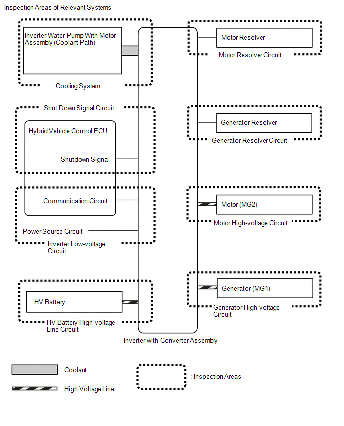 Inspection Details of Relevant Systems
 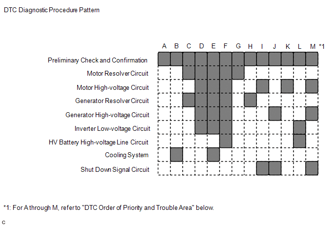 Inspection Details of Relevant Systems