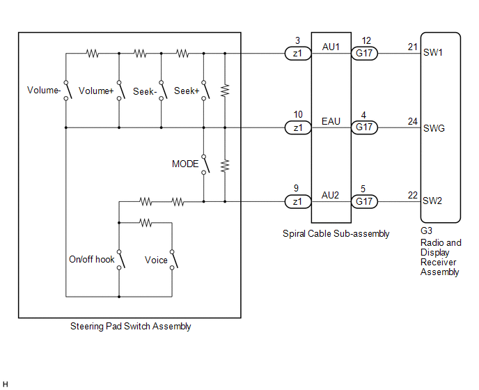
DESCRIPTION This circuit sends an operation signal from the steering pad switch assembly to the radio and display receiver assembly. If there is an open in the circuit, the audio system cannot be operated using the steering pad switch assembly. If there is a short in the circuit, the same condition as when a switch is continuously depressed occurs. Therefore, the radio and display receiver assembly cannot be operated using the steering pad switch assembly, and the radio and display receiver assembly itself will not function. WIRING DIAGRAM  CAUTION / NOTICE / HINT NOTICE: The vehicle is equipped with a Supplemental Restraint System (SRS) which includes components such as airbags. Before servicing (including removal or installation of parts), be sure to read the precaution for Supplemental Restraint System. Click here PROCEDURE
(a) Disconnect the G3 radio and display receiver assembly connector. (b) Measure the resistance according to the value(s) in the table below. Standard Resistance:
(a) Remove the steering pad switch assembly. Click here (b) Inspect the steering pad switch assembly. Click here
(a) Remove the spiral cable sub-assembly. Click here (b) Inspect the spiral cable sub-assembly. Click here
|
Toyota Avalon (XX50) 2019-2022 Service & Repair Manual > Blind Spot Monitor System(for Gasoline Model): Blind Spot Monitor Master Module (C1AB6)
DESCRIPTION This DTC is stored when the blind spot monitor sensor RH detects an internal malfunction. DTC No. Detection Item DTC Detection Condition Trouble Area C1AB6 Blind Spot Monitor Master Module The blind spot monitor sensor RH (master) detects an internal malfunction Blind spot monitor sensor ...