Toyota Avalon Service & Repair Manual: Voice Guidance Circuit between Radio Receiver and Stereo Component Amplifier

Toyota Avalon Service & Repair Manual / Audio, Visual, Telematics / Audio / Video / Audio And Visual System(for Gasoline Model) / Voice Guidance Circuit between Radio Receiver and Stereo Component Amplifier

DESCRIPTION

This circuit is used when the voice switch of the steering pad switch assembly is pushed.

Using this circuit, the radio and display receiver assembly sends signals to the stereo component amplifier assembly.

WIRING DIAGRAM
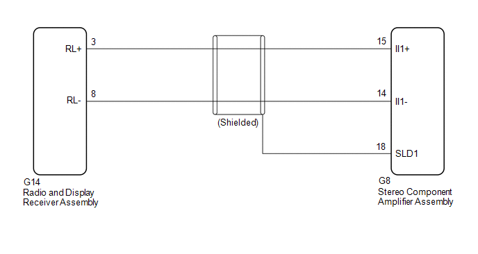
PROCEDURE

1.

CHECK HARNESS AND CONNECTOR (RADIO AND DISPLAY RECEIVER ASSEMBLY - STEREO COMPONENT AMPLIFIER ASSEMBLY)

(a) Disconnect the G14 radio and display receiver assembly connector.

(b) Disconnect the G8 stereo component amplifier assembly connector.

(c) Measure the resistance according to the value(s) in the table below.

Standard Resistance:

Tester connection

Condition

Specified condition

G14-3 (RL+) - G8-15 (II1+)

Always

Below 1 Ω

G14-8 (RL-) - G8-14 (II1-)

Always

Below 1 Ω

G8-18 (SLD1) - Body ground

Always

10 kΩ or higher

G14-3 (RL+) or G8-15 (II1+) - Body ground

Always

10 kΩ or higher

G14-8 (RL-) or G8-14 (II1-) - Body ground

Always

10 kΩ or higher

OK

PROCEED TO NEXT SUSPECTED AREA SHOWN IN PROBLEM SYMPTOMS TABLE

NG

REPAIR OR REPLACE HARNESS OR CONNECTOR

    Vehicle Speed Signal Circuit between Stereo Component Amplifier and Combination Meter

    Voice Guidance does not Function

    See More:

    Toyota Avalon Owners Manual > Do-it-yourself maintenance: Engine compartment
    Fuse boxes (if equipped) Engine oil filler cap Engine oil level dipstick Brake fluid reservoir Battery Radiator Electric cooling fan Condenser Engine coolant reservoir Washer fluid tank Engine oil With the engine at operating temperature and turned off, check the oil level on the dipstick. ■ Chec ...

    Toyota Avalon Owners Manual

    Toyota Avalon Service & Repair Manual

    © 2023 Copyright www.tavalon.net
    0.0205