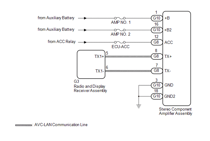
DESCRIPTION The radio and display receiver assembly and stereo component amplifier assembly are connected via AVC-LAN communication line. |
DTC No. | Detection Item |
DTC Detection Condition | Trouble Area | |
B15D3 | Stereo Component Amplifier Disconnected |
When either of the following conditions is met:
- Stereo component amplifier assembly is/was not connected while the power switch is/was on (IG) or on (ACC)
- Communication between the master unit and the stereo component amplifier assembly is not possible when the engine is started.
|
- Stereo component amplifier assembly power source circuit
- AVC-LAN circuit between radio and display receiver assembly and stereo component amplifier assembly
- Stereo component amplifier assembly
- Radio and display receiver assembly
- Harness or connector
| HINT: The radio and display receiver assembly is the master unit. WIRING DIAGRAM
 CAUTION / NOTICE / HINT
NOTICE:
- Inspect the fuses for circuits related to this system before performing the following procedure.
- Depending on the parts that are replaced during vehicle inspection or
maintenance, performing initialization, registration or calibration may
be needed. Refer to Precaution for Audio and Visual System.
Click here 
- When replacing the radio and display receiver assembly, always replace
it with a new one. If a radio and display receiver assembly which was
installed to another vehicle is used, the following may occur:
- A communication malfunction DTC may be stored.
- The radio and display receiver assembly may not operate normally.
PROCEDURE (a) If DTC B15C3 is output, perform troubleshooting for DTC B15C3 first.
|
Result | Proceed to | |
DTC B15C3 is not output. |
A | | DTC B15C3 is output. |
B |
| B |
 | GO TO DTC B15C3 |
|
A |
 | |
| 2. |
CHECK OPTIONAL COMPONENTS (INCLUDING ASSOCIATED WIRING) |
(a) Check that optional components (including associated wiring) which generate radio waves are not installed.
|
Result | Proceed to | |
Optional components (including associated wiring) are installed. |
A | | Optional components (including associated wiring) are not installed. |
B |
HINT:
- Electrical noise from radio waves generated by optional components or
the wiring for those components may affect AVC-LAN communication.
- This DTC may be stored when an AVC-LAN communication error occurs due to electrical noise.
| B |
| GO TO STEP 4 |
|
A | |
| |
| 3. |
REMOVE OPTIONAL COMPONENTS (INCLUDING ASSOCIATED WIRING) |
(a) Remove optional components (including associated wiring). NOTICE:
Do not remove optional components or associated wiring without the permission of the customer.
|
NEXT | |
| |
(a) Clear the DTCs. Body Electrical > Navigation System > Clear DTCs
(b) Recheck for DTCs and check that no DTCs are output. Body Electrical > Navigation System > Trouble Codes
OK: No DTCs are output.
| OK | |
END |
|
NG | |
| |
| 5. |
CHECK HARNESS AND CONNECTOR (STEREO COMPONENT AMPLIFIER ASSEMBLY POWER SOURCE) |
(a) Disconnect the G10 and G8 stereo component amplifier assembly connectors.
(b) Measure the resistance according to the value(s) in the table below.
Standard Resistance: |
Tester Connection | Condition |
Specified Condition | |
G10-3 (GND) - Body ground |
Always | Below 1 Ω | |
G10-18 (GND2) - Body ground |
Always | Below 1 Ω |
(c) Measure the voltage according to the value(s) in the table below. Standard Voltage: |
Tester Connection | Condition |
Specified Condition | |
G10-1 (+B) - G10-3 (GND) |
Power switch off | 11 to 14 V | |
G10-16 (+B2) - G10-3 (GND) |
Power switch off | 11 to 14 V | |
G8-12 (ACC) - G10-3 (GND) |
Power switch on (ACC) |
11 to 14 V |
| NG |
| REPAIR OR REPLACE HARNESS OR CONNECTOR |
|
OK | |
| |
| 6. |
CHECK HARNESS AND CONNECTOR (RADIO AND DISPLAY RECEIVER ASSEMBLY - STEREO COMPONENT AMPLIFIER ASSEMBLY) |
(a) Disconnect the G3 radio and display receiver assembly connector. (b) Disconnect the G8 stereo component amplifier assembly connector.
(c) Measure the resistance according to the value(s) in the table below.
Standard Resistance: |
Tester Connection | Condition |
Specified Condition | |
G3-5 (TX1+) - G8-8 (TX+) |
Always | Below 1 Ω | |
G3-6 (TX1-) - G8-7 (TX-) |
Always | Below 1 Ω | |
G3-5 (TX1+) or G8-8 (TX+) - Body ground |
Always | 10 kΩ or higher | |
G3-6 (TX1-) or G8-7 (TX-) - Body ground |
Always | 10 kΩ or higher |
| NG |
| REPAIR OR REPLACE HARNESS OR CONNECTOR |
|
OK | |
| |
| 7. |
REPLACE STEREO COMPONENT AMPLIFIER ASSEMBLY |
(a) Replace the stereo component amplifier assembly with a new or known good one.
Click here (b) Clear the DTCs. Body Electrical > Navigation System > Clear DTCs
(c) Recheck for DTCs and check that no DTCs are output. Body Electrical > Navigation System > Trouble Codes
OK: No DTCs are output.
| OK | |
END |
| NG |
| REPLACE RADIO AND DISPLAY RECEIVER ASSEMBLY | | 

