Components COMPONENTS ILLUSTRATION 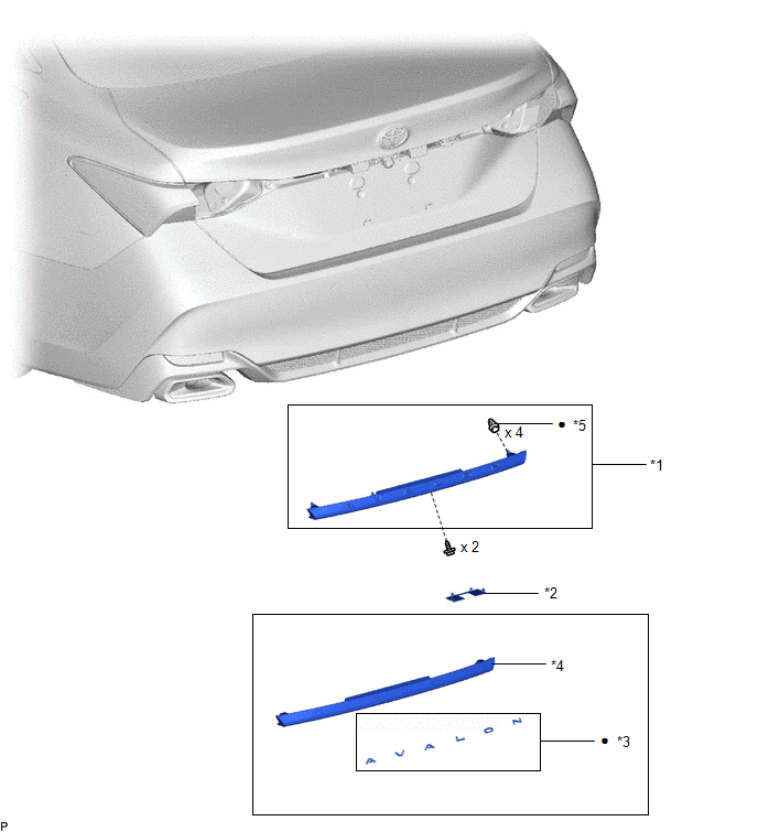
Disassembly DISASSEMBLY PROCEDURE 1. REMOVE NO. 2 LUGGAGE COMPARTMENT DOOR NAME PLATE Click here
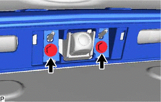
Installation INSTALLATION PROCEDURE 1. INSTALL LUGGAGE COMPARTMENT DOOR OUTSIDE GARNISH SUB-ASSEMBLY (a) Install 4 new clips to the luggage compartment door outside garnish. (b) Engage the 4 clips as shown in the illustration. 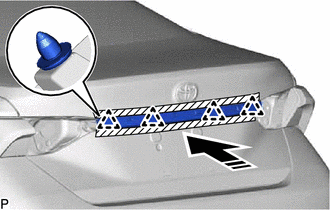
(c) Install the luggage compartment door outside garnish sub-assembly with the 2 screws. 2. INSTALL NO. 2 BACK DOOR OUTSIDE GARNISH
3. INSTALL REAR LIGHT ASSEMBLY LH Click here
4. INSTALL REAR LIGHT ASSEMBLY RH HINT: Use the same procedure as for the LH side. Reassembly REASSEMBLY PROCEDURE 1. INSTALL NO. 2 LUGGAGE COMPARTMENT DOOR NAME PLATE Click here
Removal REMOVAL PROCEDURE 1. REMOVE REAR LIGHT ASSEMBLY LH Click here
2. REMOVE REAR LIGHT ASSEMBLY RH HINT: Use the same procedure as for the LH side. 3. REMOVE NO. 2 BACK DOOR OUTSIDE GARNISH
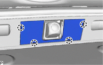
4. REMOVE LUGGAGE COMPARTMENT DOOR OUTSIDE GARNISH SUB-ASSEMBLY (a) Apply protective tape around the luggage compartment door outside garnish sub-assembly. 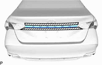
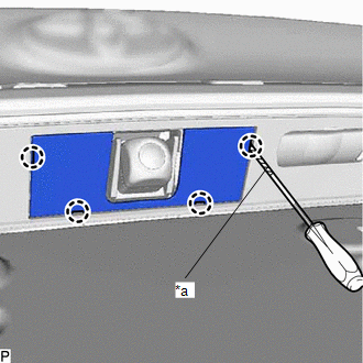
(c) Using a moulding remover, disengage the 4 clips and remove the luggage compartment door outside garnish sub-assembly as shown in the illustration. 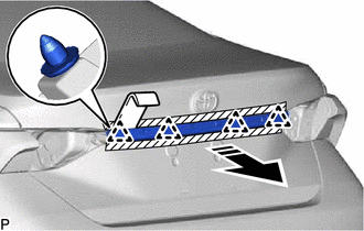
(d) Remove the 4 clips from the luggage compartment door outside garnish. |
Toyota Avalon (XX50) 2019-2022 Service & Repair Manual > Dynamic Radar Cruise Control System(for Hv Model): Front Radar Sensor (C1A10)
DESCRIPTION The driving support ECU assembly uses the millimeter wave radar sensor assembly to detect obstacles in front of the vehicle. When the driving support ECU assembly receives information that there is a malfunction in the millimeter wave radar sensor assembly, DTC C1A10 is stored. DTC No. D ...