Components COMPONENTS ILLUSTRATION 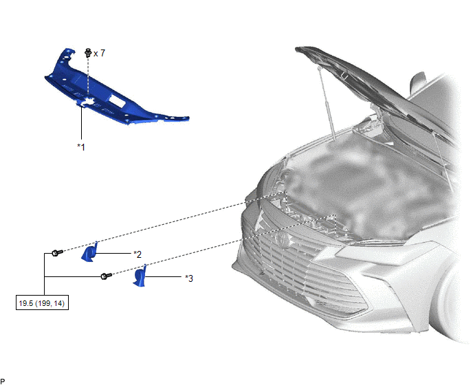
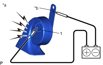
Inspection INSPECTION PROCEDURE 1. INSPECT HIGH PITCHED HORN ASSEMBLY
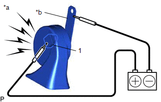
2. INSPECT LOW PITCHED HORN ASSEMBLY
Installation INSTALLATION PROCEDURE 1. INSTALL LOW PITCHED HORN ASSEMBLY (a) Connect the connector. (b) Install the low pitched horn assembly with the bolt. Torque: 19.5 N·m {199 kgf·cm, 14 ft·lbf} 2. INSTALL HIGH PITCHED HORN ASSEMBLY (a) Connect the connector. (b) Install the high pitched horn assembly with the bolt. Torque: 19.5 N·m {199 kgf·cm, 14 ft·lbf} 3. INSTALL COOL AIR INTAKE DUCT SEAL Click here Removal REMOVAL PROCEDURE 1. REMOVE COOL AIR INTAKE DUCT SEAL Click here
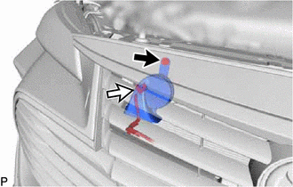
2. REMOVE HIGH PITCHED HORN ASSEMBLY
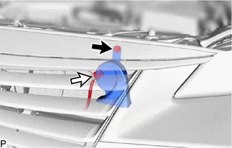
(b) Disconnect the connector to remove the high pitched horn assembly. 3. REMOVE LOW PITCHED HORN ASSEMBLY
(b) Disconnect the connector to remove the low pitched horn assembly. |
Toyota Avalon (XX50) 2019-2022 Service & Repair Manual > Sfi System: Bank 1 Air-Fuel Ratio Imbalance (Port) (P11EA00-P11EF00,P11F000,P11F100,P219A00-P219F00,P21A000,P21A100)
DESCRIPTION Refer to DTC P030000. Click here Refer to DTC P219519. Click here DTC No. Detection Item DTC Detection Condition Trouble Area MIL Memory Note P11EA00 Bank 1 Air-Fuel Ratio Imbalance (Port) The difference in air fuel ratios between the cylinders exceeds the threshold (2 trip detection log ...