Toyota Avalon (XX50) 2019-2022 Service & Repair Manual: Reverse Signal Circuit

DESCRIPTION

The radio and display receiver assembly receives a reverse signal from the BKUP LP relay.

WIRING DIAGRAM
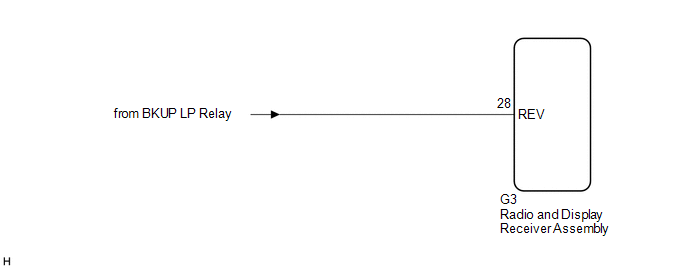
PROCEDURE

1.

CHECK BACK-UP LIGHT

(a) Move the shift lever to R and check if the back-up lights come on.

OK:

The back-up lights come on.

NG

GO TO LIGHTING SYSTEM

OK

2.

CHECK HARNESS AND CONNECTOR (REVERSE SIGNAL)

(a) Disconnect the G3 radio and display receiver assembly connector.

(b) Measure the voltage according to the value(s) in the table below.

Standard Voltage:

Tester Connection

Condition

Specified Condition

G3-28 (REV) - Body ground

Power switch on (IG)

Shift lever in R

11 to 14 V

G3-28 (REV) - Body ground

Power switch on (IG)

Shift lever not in R

Below 1 V

OK

PROCEED TO NEXT SUSPECTED AREA SHOWN IN PROBLEM SYMPTOMS TABLE

NG

REPAIR OR REPLACE HARNESS OR CONNECTOR

    Registered Device cannot be Deleted

    Satellite Radio Broadcast cannot be Received

    See More:

    Toyota Avalon (XX50) 2019-2022 Service & Repair Manual > Sfi System: Throttle / Pedal Position Sensor / Switch "A" Circuit Voltage Out of Range (P01201C)
    DESCRIPTION Refer to DTC P012011. Click here DTC No. Detection Item DTC Detection Condition Trouble Area MIL Memory Note P01201C Throttle / Pedal Position Sensor / Switch "A" Circuit Voltage Out of Range The difference between the output voltage of VTA1 and VTA2 is less than 0.8 V, or higher than 1. ...

    Toyota Avalon (XX50) 2019-2022 Owners Manual

    Toyota Avalon (XX50) 2019-2022 Service & Repair Manual

    © 2025 Copyright www.tavalon.net
    0.0339