DESCRIPTION The radio and display receiver assembly sends a sound signal to the stereo component amplifier assembly via this circuit. The sound signal that is sent is amplified by the stereo component amplifier assembly, and then is sent to the speakers. If there is an open or short in this circuit, sound cannot be heard from the speakers even if the stereo component amplifier assembly or speakers are not malfunctioning. WIRING DIAGRAM 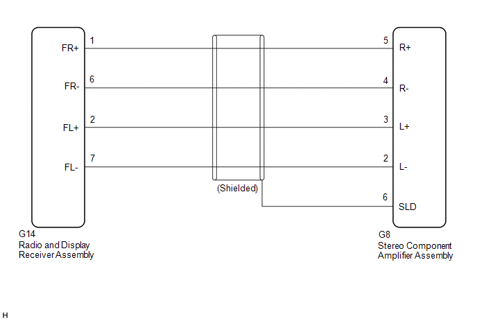 PROCEDURE
(a) Disconnect the G14 radio and display receiver assembly connector. (b) Disconnect the G8 stereo component amplifier assembly connector. (c) Measure the resistance according to the value(s) in the table below. Standard Resistance:
|
Toyota Avalon (XX50) 2019-2022 Service & Repair Manual > Sfi System: System Too Lean Bank 1 (P017100,P017200,P117000,P117B00)
DESCRIPTION The fuel trim is related to the feedback compensation value, not to the basic injection duration. The fuel trim consists of both the short-term and long-term fuel trims. The short-term fuel trim is fuel compensation that is used to constantly maintain the air fuel ratio at stoichiometric ...


