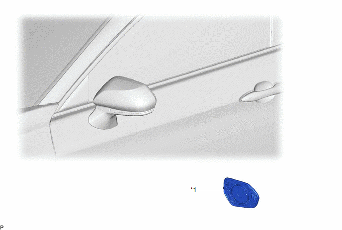
Components COMPONENTS ILLUSTRATION
Inspection INSPECTION PROCEDURE
1. INSPECT OUTER MIRROR RH
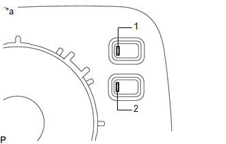
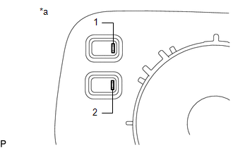
| (a) Check the outer mirror heater operation. (1) Measure the resistance according to the value(s) in the table below.
Standard Resistance: |
Tester Connection | Condition |
Specified Condition | |
1 - 2 | 25°C (77°F) |
10 to 17 Ω | If the result is not as specified, replace the outer mirror RH. |
 |
|
*a | Component without harness connected
(Outer Mirror RH) | | |
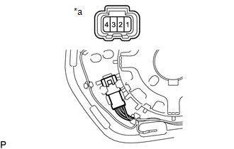
(b) Check the operation of the outer rear view mirror indicator. NOTICE:
Do not apply a voltage of more than 4.5 V. (1) Connect 3 new 1.5 V dry-cell batteries in series.
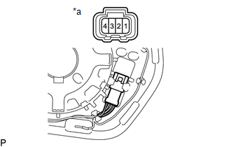
| (2) Apply 4.5 V battery voltage to the terminals of the connector, and check that the outer rear view mirror indicator comes on.
OK: |
Tester Connection | Specified Condition | |
4.5 V battery negative (-) → Terminal 4 4.5 V battery positive (+) → Terminal 1 |
Outer rear view mirror indicator comes on |
If the result is not as specified, replace the outer mirror RH. |
 |
|
*a | Component without harness connected
(Outer Mirror RH) | | |
2. INSPECT OUTER MIRROR LH
| (a) Check the outer mirror heater operation. (1) Measure the resistance according the value(s) in the table below.
Standard Resistance: |
Tester Connection | Condition |
Specified Condition | |
1 - 2 | 25°C (77°F) |
10 to 17 Ω | If the result is not as specified, replace the outer mirror LH. |
 |
|
*a | Component without harness connected
(Outer Mirror LH) | | |
(b) Check the operation of the outer rear view mirror indicator. NOTICE:
Do not apply a voltage of more than 4.5 V. (1) Connect 3 new 1.5 V dry-cell batteries in series.
| (2) Apply 4.5 V battery voltage to the terminals of the connector, and check that the outer rear view mirror indicator comes on.
OK: |
Tester Connection | Specified Condition | |
4.5 V battery negative (-) → Terminal 4 4.5 V battery positive (+) → Terminal 1 |
Outer rear view mirror indicator comes on |
If the result is not as specified, replace the outer mirror LH. |
 |
|
*a | Component without harness connected
(Outer Mirror LH) | | | Installation INSTALLATION CAUTION / NOTICE / HINT
HINT:
- Use the same procedure for the RH side and LH side.
- The following procedure is for the LH side.
PROCEDURE 1. INSTALL OUTER MIRROR (a) Connect each connector.
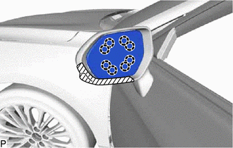
| (b) Engage the 8 claws to install the outer mirror. NOTICE:
Do not push the outer mirror with excessive force. Doing so may break the mirror surface. |
| Removal REMOVAL CAUTION / NOTICE / HINT
HINT:
- Use the same procedure for the RH side and LH side.
- The following procedure is for the LH side.
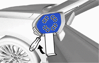
PROCEDURE 1. REMOVE OUTER MIRROR (a) Apply protective tape to the areas shown in the illustration.
 |
Protective Tape | (b) Push the upper part of the mirror surface and tilt it.
NOTICE: Do not push the outer mirror with excessive force. Doing so may cause the actuator to come off or break the mirror surface.
(c) Using a moulding remover and screwdriver, disengage the 8 claws as shown in the illustration.
| (d) Disconnect each connector to remove the outer mirror. |
| |