Components COMPONENTS ILLUSTRATION 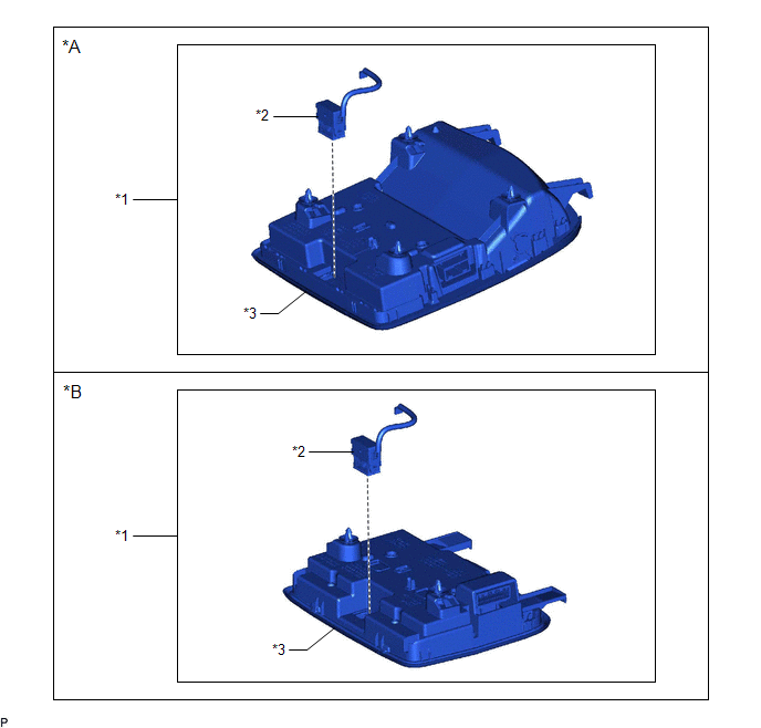
Installation INSTALLATION PROCEDURE 1. INSTALL TELEPHONE MICROPHONE ASSEMBLY (a) for Normal Roof: (1) Engage the 2 claws to install the telephone microphone assembly to the roof console box sub-assembly as shown in the illustration. 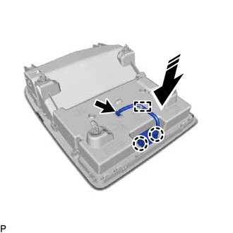
(2) Engage the clamp. (3) Connect the connector. (b) for Moon Roof: (1) Engage the 2 claws to install the telephone microphone assembly to the roof console box sub-assembly as shown in the illustration. 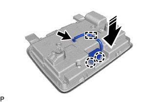
(2) Engage the clamp. (3) Connect the connector. 2. INSTALL ROOF CONSOLE BOX ASSEMBLY Click here Removal REMOVAL PROCEDURE 1. REMOVE ROOF CONSOLE BOX ASSEMBLY Click here
2. REMOVE TELEPHONE MICROPHONE ASSEMBLY (a) for Normal Roof: (1) Disconnect the connector. 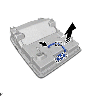
(2) Disengage the clamp. (3) Disengage the 2 claws and remove the telephone microphone assembly from the roof console box sub-assembly as shown in the illustration. (b) for Moon Roof: (1) Disconnect the connector. 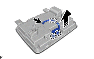
(2) Disengage the clamp. (3) Disengage the 2 claws and remove the telephone microphone assembly from the roof console box sub-assembly as shown in the illustration. |
Toyota Avalon (XX50) 2019-2022 Service & Repair Manual > Front Camera: Adjustment (sequential Recognition)
ADJUSTMENT (SEQUENTIAL RECOGNITION) CAUTION / NOTICE / HINT NOTICE: Make sure to read Before Starting Adjustment before proceeding with work. Click here PROCEDURE 1. SECURE APPROPRIATE AREA FOR PERFORMING LEARNING (a) Park the vehicle on a level surface. HINT: Make sure that the target recognition a ...


