REMOVAL CAUTION / NOTICE / HINT The necessary procedures (adjustment, calibration, initialization or registration) that must be performed after parts are removed and installed, or replaced during radio setting condenser removal/installation are shown below. Necessary Procedure After Parts Removed/Installed/Replaced (for Gasoline Model)
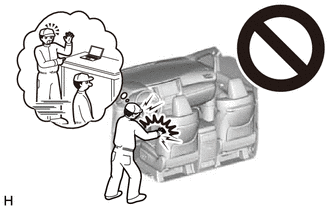
CAUTION: Some of these service operations affect the SRS airbag system. Read the precautionary notices concerning the SRS airbag system before servicing. Click here
 Necessary Procedure After Parts Removed/Installed/Replaced (for HV Model) Necessary Procedure After Parts Removed/Installed/Replaced (for HV Model)
CAUTION: Some of these service operations affect the SRS airbag system. Read the precautionary notices concerning the SRS airbag system before servicing. Click here
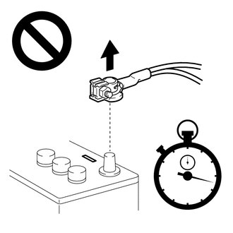
PROCEDURE 1. PRECAUTION NOTICE: After turning the engine switch (for Gasoline Model) or power switch (for HV Model) off, waiting time may be required before disconnecting the cable from the negative (-) auxiliary battery terminal. Therefore, make sure to read the disconnecting the cable from the negative (-) auxiliary battery terminal notices before proceeding with work. Click here
2. REMOVE LUGGAGE TRIM SERVICE HOLE COVER (for HV Model) Click here 3. DISCONNECT CABLE FROM NEGATIVE AUXILIARY BATTERY TERMINAL for A25A-FXS: Click here for 2GR-FKS: Click here CAUTION:
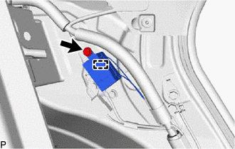
 4. REMOVE SPARE WHEEL COVER ASSEMBLY (w/ Seat Heater System) Click here 5. REMOVE LUGGAGE COMPARTMENT INNER TRIM PAD (w/ Seat Heater System) Click here 6. DISCONNECT REAR CENTER SEAT OUTER BELT ASSEMBLY Click here 7. REMOVE REAR SEAT CUSHION ASSEMBLY Click here 8. REMOVE REAR SEAT CUSHION LOCK HOOK Click here 9. REMOVE REAR SIDE SEATBACK ASSEMBLY LH Click here 10. REMOVE RADIO SETTING CONDENSER (for High Mounted Stop Light) NOTICE: When a terminal cover is removed, the radio setting condenser must be replaced because the terminal covers and condenser are supplied as a set.
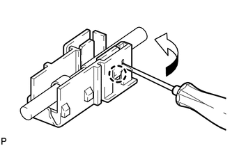
(b) Disengage the clamp and disconnect the radio setting condenser with wire harness from the vehicle body. (c) Disengage the claw and pull out the cover as shown in the illustration. 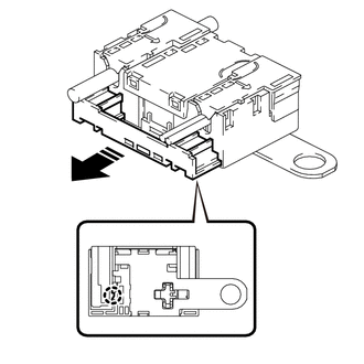
(d) Using a screwdriver, disengage the 6 claws and remove the 2 terminal covers with wire harness from the condenser as shown in the illustration. 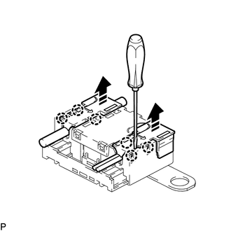
(f) Remove the 2 terminal covers from the wire harness. NOTICE:
11. DISCONNECT REAR DOOR OPENING TRIM WEATHERSTRIP LH Click here
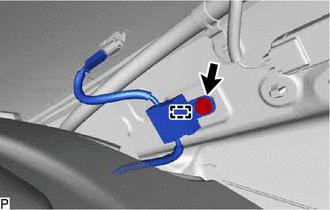
12. REMOVE ROOF SIDE RAIL GARNISH ASSEMBLY LH Click here 13. REMOVE ROOF SIDE INNER GARNISH LH Click here 14. REMOVE RADIO SETTING CONDENSER (for Window Defogger) NOTICE: When the terminal cover is removed, the radio setting condenser must be replaced because the terminal cover and condenser are supplied as a set.
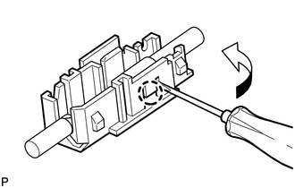
(b) Disengage the clamp and disconnect the radio setting condenser with wire harness from the vehicle body. (c) Using a screwdriver, disengage the 3 claws and remove the terminal cover with wire harness from the condenser as shown in the illustration. 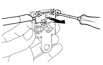
(e) Remove the terminal cover from the wire harness. NOTICE:
| ||||||||||||||||||||||||||||||||||||||||||||||||||||||||||
Toyota Avalon (XX50) 2019-2022 Service & Repair Manual > Intuitive Parking Assist System(for Gasoline Model): Operation Check
OPERATION CHECK Self-diagnosis System (a) If the clearance warning ECU assembly detects that an ultrasonic sensor is malfunctioning, a malfunction indication is displayed on the combination meter assembly and combination meter assembly. Malfunctioning Item Detection Condition Warning Message (Multi- ...