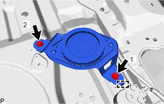
INSTALLATION PROCEDURE 1. INSTALL SPEAKER ASSEMBLY WITH BRACKET NOTICE: Do not touch the speaker cone. (a) for LH Side: (1) Connect the connector.
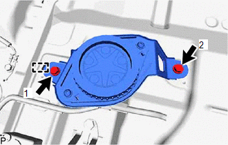
(b) for RH Side:
(2) Connect the connector. 2. INSTALL NO. 1 UPPER BACK PANEL HOLE COVER (a) Install the No. 1 upper back panel hole cover as shown in the illustration. 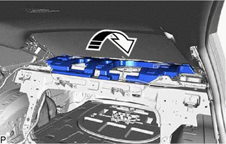
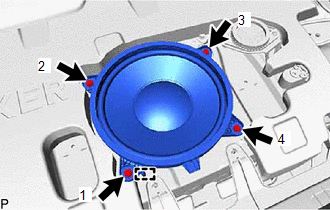
3. INSTALL ROOM PARTITION BOARD RH Click here 4. INSTALL ROOM PARTITION BOARD LH Click here 5. INSTALL LUGGAGE COMPARTMENT INNER TRIM PAD (w/o Seat Heater System) Click here 6. INSTALL SPARE WHEEL COVER ASSEMBLY (w/o Seat Heater System) Click here 7. INSTALL REAR NO. 3 SPEAKER ASSEMBLY NOTICE: Do not touch the speaker cone.
(b) Connect the connector. 8. INSTALL PACKAGE TRAY TRIM PANEL ASSEMBLY Click here 9. INSTALL REAR SEAT SHOULDER BELT COVER Click here 10. INSTALL CENTER STOP LIGHT SET Click here 11. CONNECT REAR SEAT 3 POINT TYPE BELT ASSEMBLY LH Click here 12. CONNECT REAR SEAT 3 POINT TYPE BELT ASSEMBLY RH HINT: Use the same procedure as for the LH side. 13. INSTALL ROOF SIDE INNER GARNISH LH Click here 14. INSTALL ROOF SIDE INNER GARNISH RH HINT: Use the same procedure as for the LH side. 15. INSTALL ROOF SIDE RAIL GARNISH ASSEMBLY LH Click here 16. INSTALL ROOF SIDE RAIL GARNISH ASSEMBLY RH HINT: Use the same procedure as for the LH side. 17. INSTALL REAR DOOR OPENING TRIM WEATHERSTRIP LH Click here 18. INSTALL REAR DOOR OPENING TRIM WEATHERSTRIP RH HINT: Use the same procedure as for the LH side. 19. INSTALL REAR SEAT ASSEMBLY Click here |
Toyota Avalon (XX50) 2019-2022 Service & Repair Manual > Motor Generator Control System: Terminals Of Ecu
TERMINALS OF ECU *1 Inverter with Converter Assembly HINT: Since the inverter with converter assembly uses waterproof connectors, the voltage and waveforms cannot be inspected directly. Standard voltage readings and waveforms are indicated for reference only. Inverter with Converter Assembly Termina ...