DESCRIPTION The combination meter assembly and steering pad switch assembly are connected via direct line. The multi-information display in the combination meter assembly are operated using the switches of the steering pad switch assembly. WIRING DIAGRAM 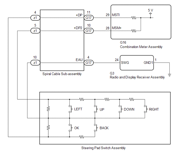 CAUTION / NOTICE / HINT NOTICE: When replacing the combination meter assembly, always replace it with a new one. If a combination meter assembly which was installed to another vehicle is used, the information stored in it will not match the information from the vehicle and a DTC may be stored. PROCEDURE
(a) Remove the steering pad switch assembly. Click here (b) Inspect the steering pad switch assembly. Click here
(a) Remove the spiral cable sub-assembly. Click here (b) Inspect the spiral cable sub-assembly. Click here
(a) Disconnect the G16 combination meter assembly connector. (b) Measure the resistance according to the value(s) in the table below. Standard Resistance:
(a) Connect the G16 combination meter assembly connector. (b) Measure the voltage according to the value(s) in the table below. Standard Voltage:
(a) Disconnect the G3 radio and display receiver assembly connector. (b) Measure the resistance according to the value(s) in the table below. Standard Resistance:
(a) Measure the resistance according to the value(s) in the table below. Standard Resistance:
|
Toyota Avalon (XX50) 2019-2022 Service & Repair Manual > Active Noise Control System: Front Left Microphone Circuit Component Internal Failure (B1AA296,B1AA31C)
DESCRIPTION These DTCs are stored when a malfunction occurs in the No. 1 active noise control microphone system. DTC No. Detection Item DTC Detection Condition Trouble Area B1AA296 Front Left Microphone Circuit Component Internal Failure Stereo component equalizer assembly detects malfunction in No. ...


