Toyota Avalon (XX50) 2019-2022 Service & Repair Manual: Dcm Power Source Circuit

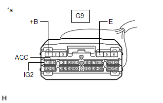
DESCRIPTION

This is the power source circuit to operate the DCM (Telematics Transceiver).

WIRING DIAGRAM

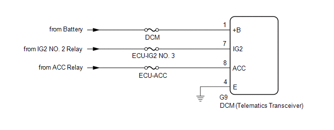
CAUTION / NOTICE / HINT

NOTICE:

Inspect the fuses for circuits related to this system before performing the following procedure.

PROCEDURE

1.

CHECK HARNESS AND CONNECTOR (DCM (TELEMATICS TRANSCEIVER) - BATTERY AND GROUND)

(a) Disconnect the G9 DCM (Telematics Transceiver) connector.

*a

Front view of wire harness connector

(to DCM (Telematics Transceiver))

(b) Measure the resistance according to the value(s) in the table below.

Standard Resistance:

Tester Connection

Condition

Specified Condition

G9-4 (E) - Body ground

Always

Below 1 Ω

(c) Measure the voltage according to the value(s) in the table below.

Standard Voltage:

Tester Connection

Condition

Specified Condition

G9-1 (+B) - G9-4 (E)

Always

11 to 14 V

G9-7 (IG2) - G9-4 (E)

Engine switch on (IG)

11 to 14 V

G9-8 (ACC) - G9-4 (E)

Engine switch on (ACC)

11 to 14 V

OK

PROCEED TO NEXT SUSPECTED AREA SHOWN IN PROBLEM SYMPTOMS TABLE

NG

REPAIR OR REPLACE HARNESS OR CONNECTOR

    Dcm Operation History

    Diagnosis System

    See More:

    Toyota Avalon (XX50) 2019-2022 Service & Repair Manual > Front Shock Absorber: Removal
    REMOVAL CAUTION / NOTICE / HINT The necessary procedures (adjustment, calibration, initialization, or registration) that must be performed after parts are removed and installed, or replaced during front shock absorber assembly removal/installation are shown below. Necessary Procedures After Parts Re ...

    Toyota Avalon (XX50) 2019-2022 Owners Manual

    Toyota Avalon (XX50) 2019-2022 Service & Repair Manual

    © 2024 Copyright www.tavalon.net
    0.0221