DESCRIPTION This is the power source circuit for the mobile wireless charger cradle assembly. WIRING DIAGRAM 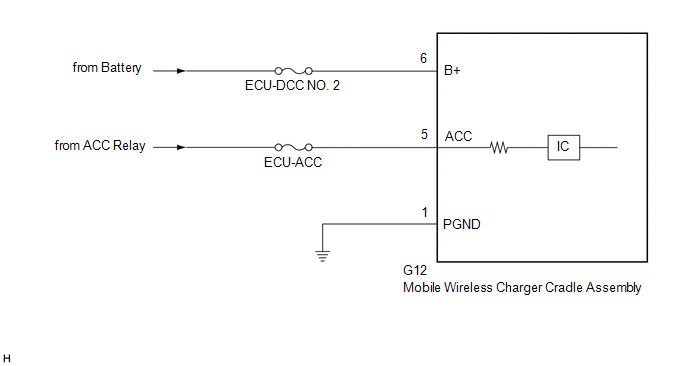 CAUTION / NOTICE / HINT NOTICE: Inspect the fuses for circuits related to this system before performing the following procedure. PROCEDURE
(a) Disconnect the G12 mobile wireless charger cradle assembly connector. (b) Measure the resistance according to the value(s) in the table below. Standard Resistance:
(c) Measure the voltage according to the value(s) in the table below. Standard Voltage:
|
Toyota Avalon (XX50) 2019-2022 Service & Repair Manual > Airbag System(for Gasoline Model): Short in P Squib (Dual Stage - 2nd Step) Circuit (B1815-B1818)
DESCRIPTION The front passenger squib 2nd step circuit consists of the airbag ECU assembly and instrument panel passenger airbag assembly. The airbag ECU assembly uses this circuit to deploy the airbag when deployment conditions are met. These DTCs are stored when a malfunction is detected in the fr ...


