Toyota Avalon (XX50) 2019-2022 Service & Repair Manual: Terminals Of Ecu

TERMINALS OF ECU

CHECK AIR CONDITIONING AMPLIFIER ASSEMBLY

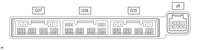
(a) Disconnect the G35 air conditioning amplifier assembly connector.

(b) Measure the voltage and resistance according to the value(s) in the table below.

HINT:

Measure the values on the wire harness side with the connector disconnected.

Terminal No. (Symbol)

Wiring Color

Terminal Description

Condition

Specified Condition

G35-2 (IG+) - Body ground

LA-GR - Body ground

Air conditioning amplifier power supply

Engine switch off

Below 1 V

G35-2 (IG+) - Body ground

LA-GR - Body ground

Air conditioning amplifier power supply

Engine switch on (IG)

11 to 14 V

G35-4 (GND) - Body ground

W-B - Body ground

Air conditioning amplifier ground

Always

Below 1 Ω

(c) Reconnect the G35 air conditioning amplifier assembly connector.

(d) Check for pulses according to the value(s) in the table below.

Terminal No. (Symbol)

Wiring Color

Terminal Description

Condition

Specified Condition

G35-24 (LOUT) - Body ground

G - Body ground

Climate control blower control signal

  • Engine switch on (IG)
  • Climate control switch (radio and display receiver assembly) (for LH) on

    (blower position)

Pulse generation

(See waveform)

G35-23 (ROUT) - Body ground

LG - Body ground

Climate control blower control signal

  • Engine switch on (IG)
  • Climate control switch (radio and display receiver assembly) (for RH) on

    (blower position)

Pulse generation

(See waveform)

G35-14 (LIN1) - Body ground

LG - Body ground

Climate control switch signal

Engine switch on (IG)

Pulse generation

(1) Waveform (Reference):
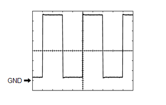
Measurement Condition

Item

Content

Tester Connection

  • G35-24 (LOUT) - Body ground
  • G35-23 (ROUT) - Body ground

Tool Setting

1 V/DIV., 0.5 ms/DIV.

Vehicle Condition

  • Engine switch on (IG)
  • Climate control switch (radio and display receiver assembly) on

    (blower position)

CLIMATE CONTROL SWITCH (RADIO AND DISPLAY RECEIVER ASSEMBLY)

(a) Disconnect the G20 climate control switch (radio and display receiver assembly) connector.

(b) Measure the voltage and resistance according to the value(s) in the table below.

HINT:

Measure the values on the wire harness side with the connector disconnected.

Terminal No. (Symbol)

Wiring Color

Terminal Description

Condition

Specified Condition

G20-2 (IG+) - Body ground

GR - Body ground

Climate control switch power supply

Engine switch off

Below 1 V

G20-2 (IG+) - Body ground

GR - Body ground

Climate control switch power supply

Engine switch on (IG)

11 to 14 V

G20-6 (GND) - Body ground

W-B - Body ground

Climate control switch ground

Always

Below 1 Ω

(c) Reconnect the G20 climate control switch (radio and display receiver assembly) connector.

(d) Check for pulses according to the value(s) in the table below.

Terminal No. (Symbol)

Wiring Color

Terminal Description

Condition

Specified Condition

G20-8 (LIN1) - Body ground

LG - Body ground

Climate control switch signal

Engine switch on (IG)

Pulse generation

    System Diagram

    Climate Control Seat System(for Hv Model)

    See More:

    Toyota Avalon (XX50) 2019-2022 Service & Repair Manual > Power Steering System(for Gasoline Model): Lost Communication with ECM / PCM "A" (U0100,U0126,U0129,U0132,U023A)
    DESCRIPTION The power steering ECU (rack and pinion power steering gear assembly) receives signals from the ECM, steering sensor, skid control ECU (brake actuator assembly), AVS ECU (absorber control ECU) and forward recognition camera via CAN communication. DTC No. Detection Item DTC Detection Cond ...

    Toyota Avalon (XX50) 2019-2022 Owners Manual

    Toyota Avalon (XX50) 2019-2022 Service & Repair Manual

    © 2024 Copyright www.tavalon.net
    0.0191