DESCRIPTION This DTC is set when the DCM (Telematics Transceiver) detects an open or short circuit in the manual (SOS) switch. |
DTC No. | Detection Item |
DTC Detection Condition | Trouble Area | |
B15C5 | Manual Button Malfunction |
Open or short circuit in manual (SOS) switch is detected. |
- DCM (Telematics Transceiver)
- Roof console box sub-assembly
- Wire harness or connector
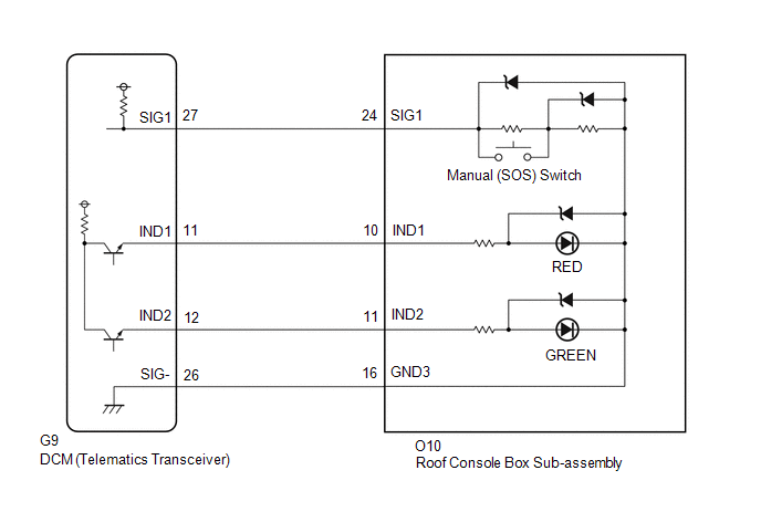
| WIRING DIAGRAM w/o Sliding Roof
 w/ Sliding Roof w/ Sliding Roof
 CAUTION / NOTICE / HINT
HINT: Before
performing this diagnostic procedure, make sure to perform Health Check
and confirm that the DCM/VIN registration information is correct. Click here
 PROCEDURE
(a) Choose the model to be inspected.
| Result |
Proceed to | | w/ Sliding Roof |
A | | w/o Sliding Roof |
B |
| B |
 | GO TO STEP 6 |
|
A |
 | |
(a) Turn the power switch off.
(b) Connect the Techstream to the DLC3. (c) Turn the power switch on (IG) and wait for 10 seconds.
(d) Turn the Techstream on. (e) Clear the DTCs. Body Electrical > Telematics > Clear DTCs
(f) Recheck for DTCs. Body Electrical > Telematics > Trouble Codes
|
Result | Proceed to | |
DTC B1570, B1571 and B15C5 are output |
A | | DTC B15C5 is output
(DTC B1570 and B1571 are not output) |
B |
| B |
| USE SIMULATION METHOD TO CHECK |
|
A | |
| |
| 3. |
INSPECT ROOF CONSOLE BOX SUB-ASSEMBLY (MANUAL (SOS) SWITCH) |
| (a) Disconnect the O10 roof console box sub-assembly connector. |
 |
|
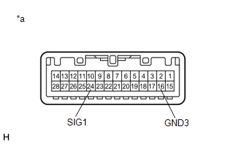
*a | Component without harness connected
(Roof Console Box Sub-assembly) | | |
(b) Measure the resistance according to the value(s) in the table below.
Standard Resistance: |
Tester Connection | Condition |
Specified Condition | |
24 (SIG1) - 16 (GND3) |
Manual (SOS) switch not pressed |
410 to 414 Ω | |
24 (SIG1) - 16 (GND3) |
Manual (SOS) switch pressed |
81 to 83 Ω |
| NG |
| REPLACE ROOF CONSOLE BOX SUB-ASSEMBLY |
|
OK | |
| |
| 4. |
CHECK HARNESS AND CONNECTOR (DCM (TELEMATICS TRANSCEIVER) - ROOF CONSOLE BOX SUB-ASSEMBLY) |
(a) Disconnect the G9 DCM (Telematics Transceiver) connector. (b) Disconnect the O10 roof console box sub-assembly connector.
(c) Measure the resistance according to the value(s) in the table below.
Standard Resistance: |
Tester Connection | Condition |
Specified Condition | |
G9-26 (SIG-) - O10-16 (GND3) |
Always | Below 1 Ω | |
G9-26 (SIG-) or O10-16 (GND3) - Body ground |
Always | 10 kΩ or higher | |
G9-27 (SIG1) - O10-24 (SIG1) |
Always | Below 1 Ω | |
G9-27 (SIG1) or O10-24 (SIG1) - Body ground |
Always | 10 kΩ or higher |
| NG |
| REPAIR OR REPLACE HARNESS OR CONNECTOR |
|
OK | |
| |
| 5. |
REPLACE DCM (TELEMATICS TRANSCEIVER) | (a) Replace the DCM (Telematics Transceiver).
Click here
NOTICE:
- The power switch must be off.
- Do not swap the DCM (Telematics Transceiver) with one from another vehicle.
| NEXT |
| PERFORM DCM ACTIVATION |
(a) Turn the power switch off.
(b) Connect the Techstream to the DLC3. (c) Turn the power switch on (IG) and wait for 10 seconds.
(d) Turn the Techstream on. (e) Clear the DTCs. Body Electrical > Telematics > Clear DTCs
(f) Recheck for DTCs. Body Electrical > Telematics > Trouble Codes
|
Result | Proceed to | |
DTC B1570, B1571 and B15C5 are output |
A | | DTC B15C5 is output
(DTC B1570 and B1571 are not output) |
B |
| B |
| USE SIMULATION METHOD TO CHECK |
|
A | |
| |
| 7. |
INSPECT ROOF CONSOLE BOX SUB-ASSEMBLY (MANUAL (SOS) SWITCH) |
| (a) Disconnect the O9 roof console box sub-assembly connector. |
 |
|
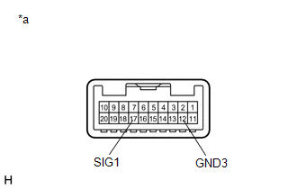
*a | Component without harness connected
(Roof Console Box Sub-assembly) | | |
(b) Measure the resistance according to the value(s) in the table below.
Standard Resistance: |
Tester Connection | Condition |
Specified Condition | |
17 (SIG1) - 12 (GND3) |
Manual (SOS) switch not pressed |
410 to 414 Ω | |
17 (SIG1) - 12 (GND3) |
Manual (SOS) switch pressed |
81 to 83 Ω |
| NG |
| REPLACE ROOF CONSOLE BOX SUB-ASSEMBLY |
|
OK | |
| |
| 8. |
CHECK HARNESS AND CONNECTOR (DCM (TELEMATICS TRANSCEIVER) - ROOF CONSOLE BOX SUB-ASSEMBLY) |
(a) Disconnect the G9 DCM (Telematics Transceiver) connector. (b) Disconnect the O9 roof console box sub-assembly connector.
(c) Measure the resistance according to the value(s) in the table below.
Standard Resistance: |
Tester Connection | Condition |
Specified Condition | |
G9-26 (SIG-) - O9-12 (GND3) |
Always | Below 1 Ω | |
G9-26 (SIG-) or O9-12 (GND3) - Body ground |
Always | 10 kΩ or higher | |
G9-27 (SIG1) - O9-17 (SIG1) |
Always | Below 1 Ω | |
G9-27 (SIG1) or O9-17 (SIG1) - Body ground |
Always | 10 kΩ or higher |
| NG |
| REPAIR OR REPLACE HARNESS OR CONNECTOR |
|
OK | |
| |
| 9. |
REPLACE DCM (TELEMATICS TRANSCEIVER) | (a) Replace the DCM (Telematics Transceiver).
Click here
NOTICE:
- The power switch must be off.
- Do not swap the DCM (Telematics Transceiver) with one from another vehicle.
| NEXT |
| PERFORM DCM ACTIVATION | | 

