|
Sender | Receiver |
Signal | Line |
|
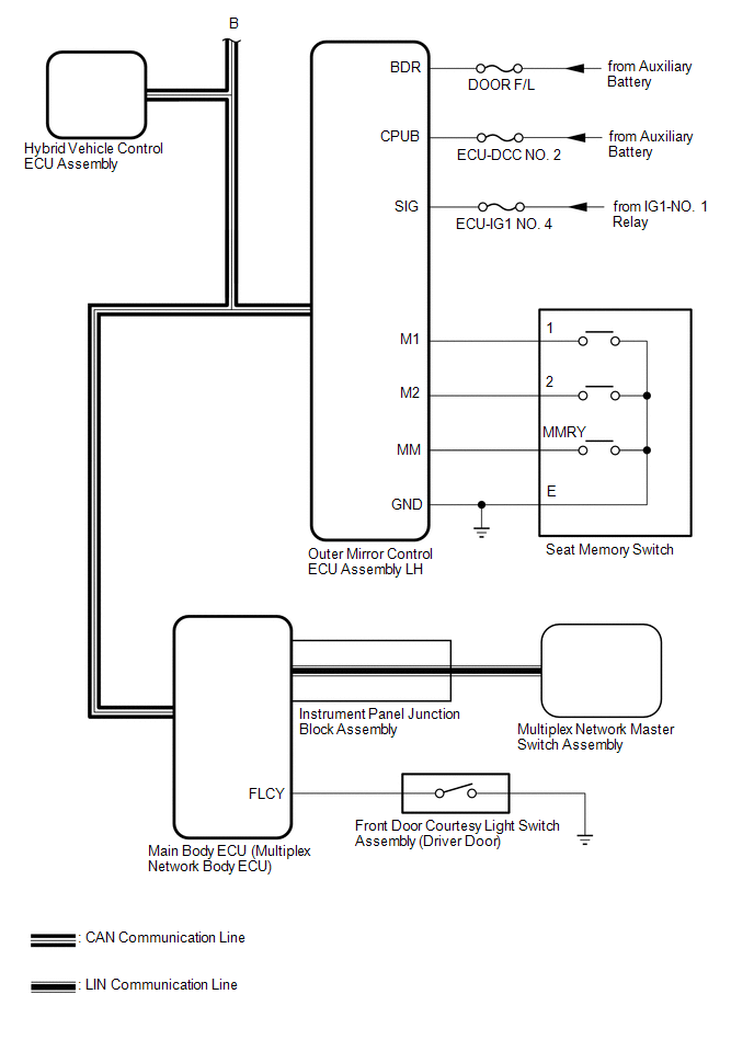
Hybrid Vehicle Control ECU Assembly |
Main Body ECU (Multiplex Network Body ECU) |
Shift position P signal |
CAN |
| Outer Mirror Control ECU Assembly LH |
Main Body ECU (Multiplex Network Body ECU) |
- M1 switch signal
- M2 switch signal
- SET switch signal
| CAN |
|
Main Body ECU (Multiplex Network Body ECU) |
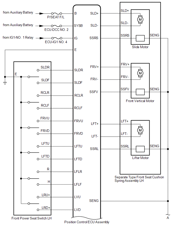
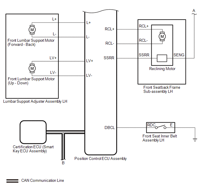
Position Control ECU Assembly |
- Shift position P signal
- Transmission information
- Driving position buzzer request
- Driver seat position request
- Driver seat position data
| CAN |
|
Certification ECU (Smart Key ECU Assembly) |
Main Body ECU (Multiplex Network Body ECU) |
- Power switch signal
- Memory call replay request
- Key identification No. 1 to No. 7 acquisition condition
| CAN |
|
Position Control ECU Assembly | Main Body ECU (Multiplex Network Body ECU) |
- State signal of driver seat
- State signal of driving position buzzer
| CAN |
|
Multiplex Network Master Switch Assembly |
Main Body ECU (Multiplex Network Body ECU) |
Door control switch signal |
LIN |
 Communication Table

