DESCRIPTION This DTC is set when the DCM (Telematics Transceiver) detects an open or short in the manual (SOS) switch green indicator circuit of the manual (SOS) switch. The manual (SOS) switch green indicator illuminates after the power switch is turned on (IG). If the safety connect system is not active, the manual (SOS) switch green indicator will turn off. If the safety connect system is active, the manual (SOS) switch green indicator will blink while communicating with the call center.
WIRING DIAGRAM w/o Sliding Roof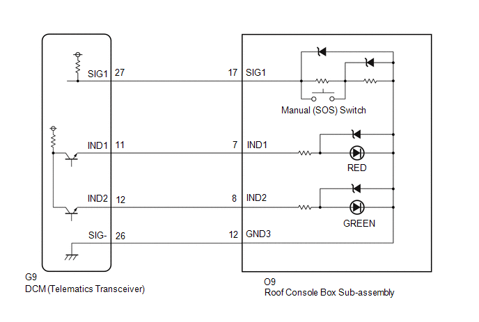 w/ Sliding Roof w/ Sliding Roof
 CAUTION / NOTICE / HINT HINT: Before performing this diagnostic procedure, make sure to perform Health Check and confirm that the DCM/VIN registration information is correct. Click here
PROCEDURE
(a) Choose the model to be inspected.
(a) Turn the power switch off. (b) Connect the Techstream to the DLC3. (c) Turn the power switch on (IG) and wait for 10 seconds. (d) Turn the Techstream on. (e) Clear the DTCs. Body Electrical > Telematics > Clear DTCs(f) Recheck for DTCs. Body Electrical > Telematics > Trouble Codes
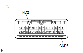
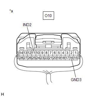
(b) Connect 2 dry-cell batteries (1.5 V each) in series. (c) Connect the positive (+) lead to terminal 11 (IND2) and the negative (-) lead to terminal 16 (GND3) of the roof console box sub-assembly connector. (d) Check if the illumination for the manual (SOS) switch green indicator comes on. OK: Green indicator comes on.
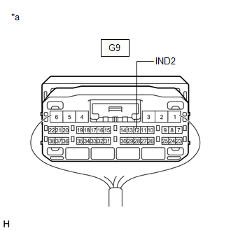
(a) Disconnect the G9 DCM (Telematics Transceiver) connector. (b) Disconnect the O10 roof console box sub-assembly connector. (c) Measure the resistance according to the value(s) in the table below. Standard Resistance:
(a) Replace the DCM (Telematics Transceiver). Click here NOTICE:
(a) Confirm the green indicator status after the power switch is turned on (IG). Click here
(b) Connect the positive lead of a voltmeter to terminal O10-11 (IND2), and the negative lead to terminal O10-16 (GND3). (c) Measure the voltage. Standard: 1.0 to 8.5 V for 2 seconds after the power switch is turned on (IG) and red indicator has turned off. 0 V when the power switch is off.
(b) Connect the positive lead of a voltmeter to terminal G9-12 (IND2), and the negative lead to body ground. (c) Measure the voltage. Standard: 1.0 to 8.5 V for 2 seconds after the power switch is turned on (IG) and red indicator has turned off. 0 V when the power switch is off.
(b) Measure the resistance according to the value(s) in the table below. Standard Resistance:
(a) Replace the DCM (Telematics Transceiver). Click here NOTICE:
(a) Turn the power switch off. (b) Connect the Techstream to the DLC3. (c) Turn the power switch on (IG) and wait for 10 seconds. (d) Turn the Techstream on. (e) Clear the DTCs. Body Electrical > Telematics > Clear DTCs(f) Recheck for DTCs. Body Electrical > Telematics > Trouble Codes
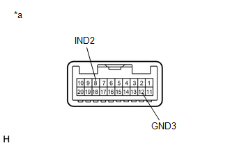
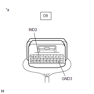
(b) Connect 2 dry-cell batteries (1.5 V each) in series. (c) Connect the positive (+) lead to terminal 8 (IND2) and the negative (-) lead to terminal 12 (GND3) of the roof console box sub-assembly connector. (d) Check if the illumination for the manual (SOS) switch green indicator comes on. OK: Green indicator comes on.
(a) Disconnect the G9 DCM (Telematics Transceiver) connector. (b) Disconnect the O9 roof console box sub-assembly connector. (c) Measure the resistance according to the value(s) in the table below. Standard Resistance:
(a) Replace the DCM (Telematics Transceiver). Click here NOTICE:
(a) Confirm the green indicator status after the power switch is turned on (IG). Click here
(b) Connect the positive lead of a voltmeter to terminal O9-8 (IND2), and the negative lead to terminal O9-12 (GND3). (c) Measure the voltage. Standard: 1.0 to 8.5 V for 2 seconds after the power switch is turned on (IG) and red indicator has turned off. 0 V when the power switch is off.
(b) Connect the positive lead of a voltmeter to terminal G9-12 (IND2), and the negative lead to body ground. (c) Measure the voltage. Standard: 1.0 to 8.5 V for 2 seconds after the power switch is turned on (IG) and red indicator has turned off. 0 V when the power switch is off.
(b) Measure the resistance according to the value(s) in the table below. Standard Resistance:
(a) Replace the DCM (Telematics Transceiver). Click here NOTICE:
|
Toyota Avalon (XX50) 2019-2022 Service & Repair Manual > Sfi System: Camshaft Position "A" - Timing Over-Advanced or System Performance Bank 1 (P001100,P001200,P002100,P002200)
DESCRIPTION Refer to DTC P001013. Click here DTC No. Detection Item DTC Detection Condition Trouble Area MIL Memory Note P001100 Camshaft Position "A" - Timing Over-Advanced or System Performance Bank 1 Intake valve timing is stuck at a certain value when in the advance range (1 trip detection logic ...