DESCRIPTION The front passenger side buckle switch circuit consists of the occupant detection ECU and front passenger side buckle switch (front seat inner belt assembly RH). DTC B1771 is stored when a malfunction is detected in the front passenger side buckle switch circuit.
WIRING DIAGRAM 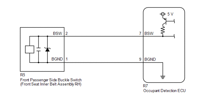 CAUTION / NOTICE / HINT NOTICE: After turning the engine switch off, waiting time may be required before disconnecting the cable from the negative (-) battery terminal. Therefore, make sure to read the disconnecting the cable from the negative (-) battery terminal notices before proceeding with work. Click here
HINT:
PROCEDURE
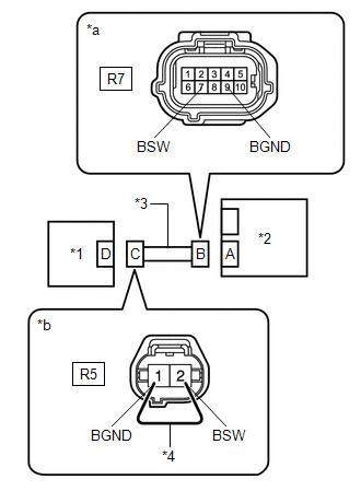
(a) Turn the engine switch off. (b) Disconnect the cable from the negative (-) battery terminal. (c) Check that the connectors are properly connected to the occupant detection ECU and front seat inner belt assembly RH. OK: The connectors are properly connected. HINT: If the connectors are not properly connected, reconnect the connectors and proceed to the next inspection. (d) Disconnect the connectors from the occupant detection ECU and front seat inner belt assembly RH. (e) Check that the terminals of the connectors are not deformed or damaged. OK: The terminals are not deformed or damaged.
(b) Turn the engine switch on (IG). (c) Measure the voltage according to the value(s) in the table below. Standard Voltage:
(d) Turn the engine switch off. (e) Disconnect the cable from the negative (-) battery terminal. (f) Using a service wire, connect terminals 2 (BSW) and 1 (BGND) of connector C. NOTICE: Do not forcibly insert the service wire into the terminals of the connector when connecting the wire. (g) Measure the resistance according to the value(s) in the table below. Standard Resistance:
(h) Disconnect the service wire from connector C. (i) Measure the resistance according to the value(s) in the table below. Standard Resistance:
(a) Connect the connectors to the occupant detection ECU and front seat inner belt assembly RH. (b) Connect the cable to the negative (-) battery terminal. (c) Turn the engine switch on (IG), and wait for at least 60 seconds. (d) Clear the DTCs stored in the occupant detection ECU. Body Electrical > Occupant Detection > Clear DTCs(e) Clear the DTCs stored in the airbag ECU assembly. Body Electrical > SRS Airbag > Clear DTCs(f) Turn the engine switch off. (g) Turn the engine switch on (IG), and wait for at least 10 seconds. (h) Check for DTCs. Body Electrical > Occupant Detection > Trouble CodesOK: DTC B1771 is not output. HINT: Codes other than DTC B1771 may be output at this time, but they are not related to this check. (i) Turn the engine switch off.
(a) Disconnect the cable from the negative (-) battery terminal. (b) Replace the front seat inner belt assembly RH with a known good one. Click here HINT: Perform the following inspection using known good parts from another vehicle if possible. (c) Connect the cable to the negative (-) battery terminal. (d) Turn the engine switch on (IG), and wait for at least 60 seconds. (e) Clear the DTCs stored in the occupant detection ECU. Body Electrical > Occupant Detection > Clear DTCs(f) Clear the DTCs stored in the airbag ECU assembly. Body Electrical > SRS Airbag > Clear DTCs(g) Turn the engine switch off. (h) Turn the engine switch on (IG), and wait for at least 10 seconds. (i) Check for DTCs. Body Electrical > Occupant Detection > Trouble CodesOK: DTC B1771 is not output. HINT: Codes other than DTC B1771 may be output at this time, but they are not related to this check. (j) Turn the engine switch off. (k) Disconnect the cable from the negative (-) battery terminal. (l) Restore the front seat inner belt assembly RH that was installed for testing to its original location. Click here
(a) Turn the engine switch off. (b) Disconnect the cable from the negative (-) battery terminal. (c) Replace the occupant detection ECU with a new one. Click here (d) Connect the cable to the negative (-) battery terminal.
(a) Using the Techstream, perform Zero Point Calibration. Click here
|
Toyota Avalon (XX50) 2019-2022 Service & Repair Manual > Oil Pump: Disassembly
DISASSEMBLY PROCEDURE 1. REMOVE CLUTCH DRUM OIL SEAL RING (a) Remove the 4 clutch drum oil seal rings from the stator shaft assembly. 2. REMOVE OIL STRAINER ASSEMBLY (a) Using a T30 "TORX" socket wrench, remove the 2 bolts and oil strainer assembly from the front oil pump cover sub-assembly. 3. REMO ...