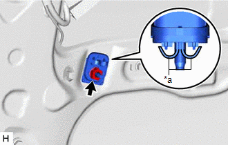
INSTALLATION PROCEDURE 1. INSTALL SIDE AIRBAG PRESSURE SENSOR (a) Check that the engine switch (for Gasoline Model) or power switch (for HV Model) is off. (b) Check that the cable is disconnected from the negative (-) auxiliary battery terminal. CAUTION: Wait at least 90 seconds after disconnecting the cable from the negative (-) auxiliary battery terminal to disable the SRS system. 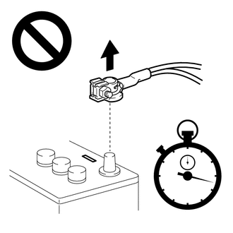 (c) Before connecting the connector, check that the position of the white housing lock is as shown in the illustration. 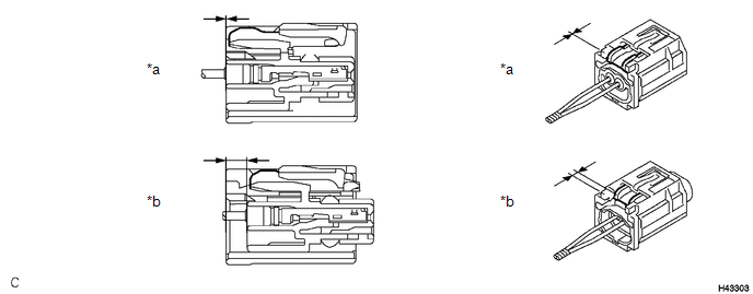
(e) Install the side airbag pressure sensor with the nut. Torque: 9.0 N·m {92 kgf·cm, 80 in·lbf} NOTICE:
(f) Connect the connector to the side airbag pressure sensor. 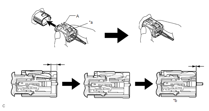
NOTICE: When connecting any airbag connector, take care not to damage the airbag wire harness. HINT:
(g) Check that there is no looseness in the installed parts of the side airbag pressure sensor. 2. INSTALL FRONT DOOR SERVICE HOLE COVER Click here
3. INSTALL FRONT DOOR TRIM BRACKET Click here 4. INSTALL FRONT DOOR TRIM BOARD SUB-ASSEMBLY Click here 5. INSTALL COURTESY LIGHT ASSEMBLY Click here 6. INSTALL MULTIPLEX NETWORK MASTER SWITCH ASSEMBLY WITH FRONT DOOR UPPER ARMREST BASE PANEL (for Driver Side) Click here 7. INSTALL POWER WINDOW REGULATOR SWITCH ASSEMBLY WITH FRONT DOOR UPPER ARMREST BASE PANEL (for Front Passenger Side) Click here 8. INSTALL FRONT DOOR TRIM POCKET COVER Click here 9. INSTALL FRONT DOOR ARMREST COVER SUB-ASSEMBLY Click here 10. CONNECT CABLE TO NEGATIVE AUXILIARY BATTERY TERMINAL for Gasoline Model: Click here for HV Model: Click here
NOTICE: When disconnecting the cable, some systems need to be initialized after the cable is reconnected. Click here 11. INSTALL LUGGAGE TRIM SERVICE HOLE COVER (for HV Model) Click here 12. INSPECT POWER WINDOW OPERATION for Gasoline Model: Click here for HV Model: Click here
13. PERFORM DIAGNOSTIC SYSTEM CHECK for Gasoline Model: Click here for HV Model: Click here
14. INSPECT SRS WARNING LIGHT for Gasoline Model: Click here
for HV Model: Click here
|
Toyota Avalon (XX50) 2019-2022 Service & Repair Manual > Can Communication System(for Hv Model): Check Bus 5 Line for Short to +B
DESCRIPTION There may be a short circuit between one of the CAN bus lines and +B when there is no resistance between terminal 15 (CA5H) of the central gateway ECU (network gateway ECU) and terminal 16 (BAT) of the DLC3, or terminal 16 (CA5L) of the central gateway ECU (network gateway ECU) and termi ...