DESCRIPTION When the theft deterrent system is switched from the armed state to the alarm sounding state, the main body ECU (multiplex network body ECU) transmits a signal to cause the horns to sound at intervals of 0.4 seconds. WIRING DIAGRAM 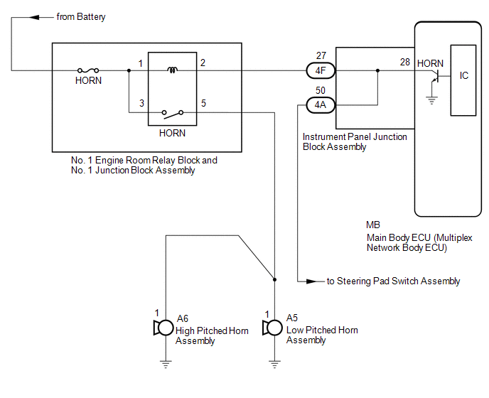 CAUTION / NOTICE / HINT NOTICE:
PROCEDURE
(a) Press the horn switch and check if the horns sound.
(a) Remove the main body ECU (multiplex network body ECU). Click here
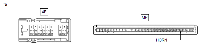
(b) Disconnect the 4F instrument panel junction block assembly connector. (c) Measure the resistance according to the value(s) in the table below. Standard Resistance:
|
Toyota Avalon (XX50) 2019-2022 Service & Repair Manual > Tire Pressure Warning System(for Gasoline Model): Receiver Error (C2176)
DESCRIPTION Tire pressure warning valve and transmitter signals are transmitted to the tire pressure warning ECU and receiver in the vehicle as radio waves. DTC No. Detection Item DTC Detection Condition Trouble Area Note C2176 Receiver Error Malfunction in the tire pressure warning ECU and receiver ...


